Rainbow Light
In previous projects, we have used different colored LEDs like red, green and blue and controlled their luminescence with microcontrollers. In this project we will see how can we produce these colors along with many others from a single LED.
An LED is made from a semi conductor material. When an electric current is passed through it, the electrons combine with the holes in the semiconductor material. When electrons combine with holes, it releases energy in the form of photons (light particles). The energy level of photon is directly related to the frequency of photon.
If the energy level of the photon matches the frequency within the spectrum of visible light, we can see the light. Different colored LEDs release photons with energy level matching different colors in visible spectrum. For example, a red LED releases photons with energy level matching the frequency of red light.
An RGB LED combines three different semiconductors within the same LED and can produce Red, Green and Blue light when a particular electrode is energized. According to the color theory, variety of colors can be produced by mixing different quantities of primary color. By combining red, green & blue, any color on the color wheel can be created. We can put this theory to practice using an RGB LED and create spectrum of colors just by 3 inputs.
Arduino microcontroller can provide 8 bit digital to analog conversion. This means it can provide 256 levels of voltages between 0 to 5 volts. This is achieved by Pulse Width Modulation (PWM) signal. You can learn more about PWM in the Learn section. Microcontroller board can provide PWM signals at pins D3, D5, D6, D9, D10 & D11. We will use 3 of these pins to provide signal; one each to control red, green & blue input of RGB led to create spectrum of colors.
Components
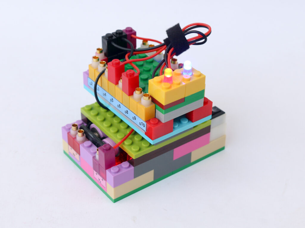
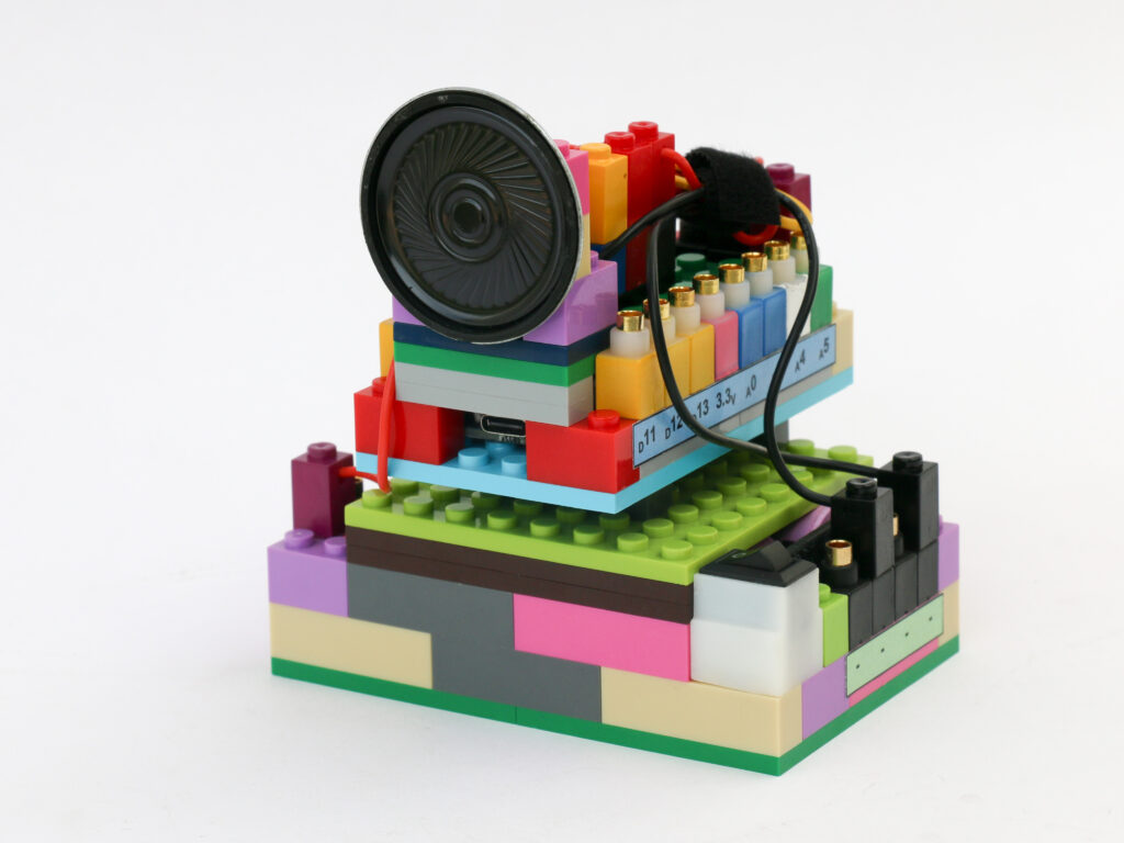
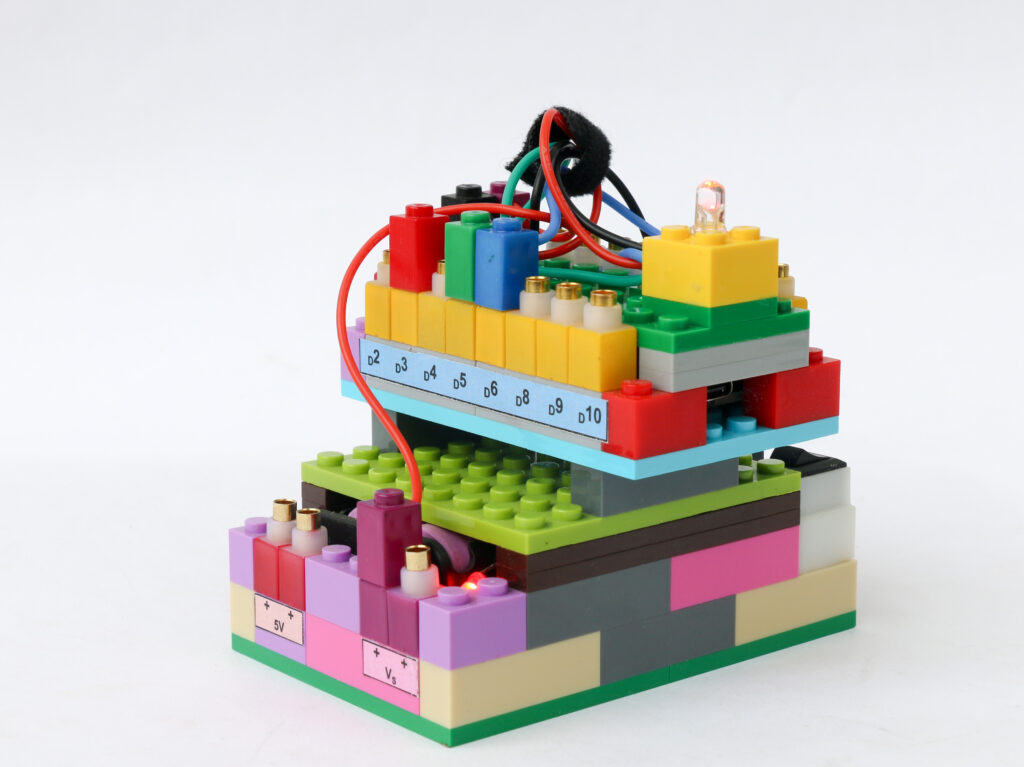
Connections
Connect the Vs pin of microcontroller to Vs pin of battery block. Connect the ground pins of microcontroller block and battery block.
Connect the red terminal of the RGB LED block to the microcontroller block pin D3. Connect the green terminal of the RGB LED block to the microcontroller block pin D5 & connect the blue terminal of the RGB block to microcontroller pin D6. Connect the negative (black) terminal of the RGB LED block to the negative pin on the battery block.
Coding
/*
   RGB LED
   This program can set various colours using RGB LED
   The RGB LED used is a common cathode type which means the common terminal needs to be grounded.
   Connect the negative pin of RGB block to battery ground pin
   Connect the red pin of RGB block to Arduino D3 pin
   Connect the green pin of RGB block to Arduino D5 pin
   Connect the blue pin of RGB block to Arduino D6 pin
*/

int redPin = 3;    // declare pin D3 as red pin
int greenPin = 5;  //declare pin D5 as green pin
int bluePin = 6;   // declare pin D6 as blue pin

void setup() {
  //declare the red, green & blue pins as outputs
  pinMode(redPin, OUTPUT);
  pinMode(greenPin, OUTPUT);
  pinMode(bluePin, OUTPUT);
  for (int i = 0; i < 256; i++) {
    setColor(i, 0, 0);  //  red
    delay(10);
  }
}

void loop() {
  for (int i = 0; i < 256; i++) {
    setColor(255, i, 0);  //  Orange & yellow
    delay(20);
  }
  for (int i = 255; i >= 0; i--) {
    setColor(i, 255, 0);  //  green
    delay(10);
  }
  for (int i = 255; i >= 0; i--) {
    setColor(0, i, (255 - i));  //  blue
    delay(10);
  }
  for (int i = 255; i >= 0; i--) {
    setColor((255 - i), 0, i);  //  violet & indigo to red
    delay(10);
  }
}

// function to set values for each 3 pins of RBG LED
void setColor(int red, int green, int blue) {
  analogWrite(redPin, red);
  analogWrite(greenPin, green);
  analogWrite(bluePin, blue);
}