Fundamentals
Robotics is multi-disciplinary field which cuts across mechanical engineering, electrical & electronics engineering and computer science. There are four main components of a Robot
Sensing
A robot needs to sense its surrounding and convert the physical stimuli to electrical signal. The components which are used to sense various physical stimuli are called sensors.
Processing
A robot needs processing power to interpret the sensing signal and create an appropriate response signal. The processors are hardware which allow mathematical and computational operations.
Actuation
Based on the response signal, a robot needs to take an action to impact its surrounding. The components which take physical action are called actuators.
Logic
The logic is a set of instructions which a robot on the sensed signal to generate response signal. The logic instructions are called software.
Along with the above components, a robot needs a mechanical structure to carry the load and enable physical movement. A robot also needs electricity to power its sensors, actuators and processor.
Makernova robotics kits contains all essential components of robotics. We will see different components and the documentation for the same below.
Arduino IDE
An integrated development environment (IDE) is a software application that provides user an ability to write and compile a code. The main parts of an IDE are as below
- Code Editor: It is typically a text editor to help write a code by highlighting syntax with visual cues.
- Code Compiler: A compiler converts human readable code into a machine understandable binary code that can be executed on an operating system or a microcontroller
- Code debugger: It is a tool to assist identifying errors by graphically pointing the locations of bugs
Arduino microcontrollers utilize its own language and utilizes its own IDE. Arduino IDE is used to code and upload those codes to microcontroller to execute different robotics projects.
Download the latest version of Arduino IDE at official website
Battery Block
The battery block is used to power all the components like microcontroller block, sensor blocks and actuator blocks.
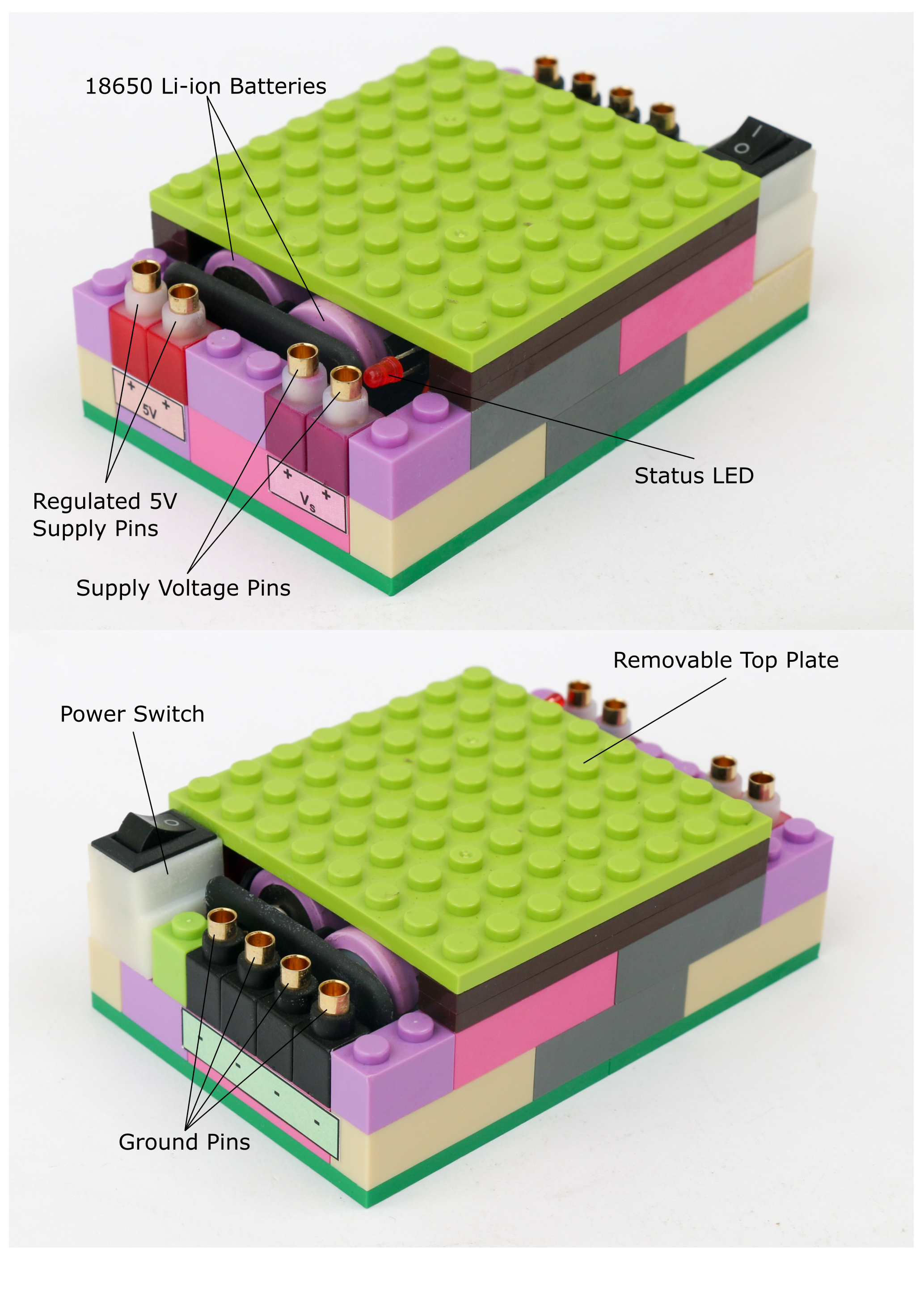
The battery block consists of 2 x 18650 Li-ion batteries connected in series. These batteries produce combined voltage of maximum 8.4V when fully charged. The battery block has two power supply levels. The Vs pins provide unregulated battery voltage. The voltage at these pins will change as the battery charge level reduces. These pins can be used to power the microcontroller block or any other actuators which require higher voltage than 5V.

Warning: Do not let the battery voltage go below 7V
The 5V pins provide regulated 5V power supply, which means it will provide constant 5V, as long as battery voltage is above 7V. These pins can be used to power any sensors or actuators which require 5V only.
The top plate of the battery block can be removed to access the batteries. Remove the batteries from the casing to charge using the Li-ion charger only.
The battery block contains a 3A fuse to protect the circuit as well as Li-ion batteries in case of short circuit. The battery block also has a status LED light which lights up when battery block is switched on. If the fuse is burned out, the status led light will not turn on.
Microcontroller Block
Microcontroller is the brain of the robot. It works on digital logic and can operate only using binary operations. The main computing part of the microcontroller is the CPU. The operations in CPU happen sequentially timed with the clock speed. Typically higher the clock speed, more calculations are done per second and hence faster execution.
The input/output ports are used to connect sensors and actuators that are controlled by the microcontroller. Since the microcontroller works on digital binary logic only, there are analog to digital (ADC) & digital to analog converter (DAC) circuits embedded in order to read and actuate analog sensors and actuators. The architecture of a typical microcontroller is shown below.

The Makernova microcontroller block houses an Arduino Nano board which uses ATmega328p microcontroller. The microcontroller runs on clock speed of 16MHz. The microcontroller operates on a digital logic of 5V. It has flash memory of 32KB, which is used to store the program. The microcontroller block has a USB-C port to communicate with a computer to upload a program as well as to power the microcontroller board.
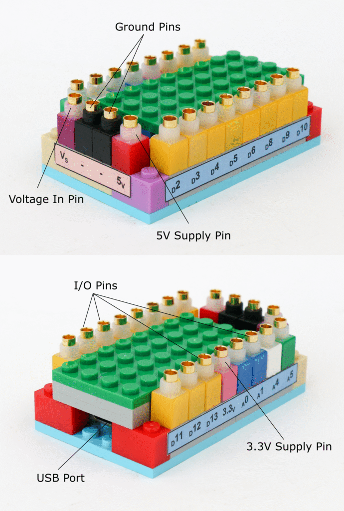
The microcontroller block has total of 15 input/output pins; 11 digital input/output pins & 4 analog input/output pins. The digital pins are addressed using their pin name in the program namely D2, D3, D4, D5, D6, D8, D9, D10, D11, D12 & D13. Similarly analog input/output pins are also addressed by using their pin name in the program namely A0, A1, A4 & A5.
The digital I/O pins are used to sense or supply 0V or 5V. 0V is also called as logic LOW and 5V as logic HIGH. Any of the digital pins can be used to read or write the digital logic, however there are some pins with special abilities as explained below.
The pins D2 & D3 are external interrupt pins, which means these can be used to trigger an interrupt service routine (ISR) when a specific event occurs, such as a change in the signal level. The interrupt stops ongoing process in the microcontroller and forces it to take action when interrupt is triggered. This is helpful to eliminate reading these pins continuously and process only when interrupt is triggered.
Pins D3, D5, D6, D9, D10 & D11 are designed to provide pulse width modulation (PWM) outputs. Since the digital I/O pins can only supply 0V or 5V, in order to create intermediate voltages, these pins provide 5V for some period and 0V for some period, causing the average voltage to be between 0V & 5V. For example, if we want to provide 2V at the digital pin, the pin can be turned high for 40% of the cycle and low for 60% of the cycle thereby making average level (5V x 0.4) + (0V x 0.6) = 2V, as illustrated below. By varying amount of time at HIGH logic different levels of output voltage is achieved.

Pins D10, D11, D12 & D13 are used in serial peripheral interface (SPI) communication. SPI communication is used for a short distance communication. Pin D10 is used as slave select (SS) which determines whether the microcontroller is acting as master (sending instructions) or slave (receiving information). Pin D11 is assigned for master in slave out (MOSI) while D12 is assigned for master out slave in (MISO). Pin D13 is assigned for providing clock (SCK) signal for SPI communication.
The analog pins have built-in 10 bit analog to digital convertor (ADC) to convert analog signal to digital signal. 10 bit ADC means the signal is scaled in 210 = 1024 levels or from 0 to 1023. 0V is read as 0 and 5V is read as 1023. All intermediate voltage levels will be read as a number between 0 & 1023.
Like digital I/O pins, some analog I/O pins also have special functions. Pins A4 & A5 are also used in inter integrated circuit (I2C) communication. The I2C communication uses a data bus and a clock bus to connect all the ICs. The A4 pin is assigned for data bus (SDA) and A5 pin is assigned for clock bus (SCK).
Warning: Each I/O pin can provide maximum 20mA current. Higher current draw will damage the microcontroller board
Along with the I/O pins, the microcontroller block also has power and ground pins. The microcontroller board can be powered by a battery block by connecting the supply voltage pin “Vs” to microcontroller power supply pin “Vs” and battery ground pin connected to microcontroller block ground pin.
The 5V pin on the microcontroller board can act as both input or output power. Instead of powering the microcontroller block from “Vs” pin, the 5V pin on microcontroller can be connected to battery block 5V supply pin. However it is recommended to power the microcontroller this way because the 5V pin can be used to power other components like sensors.
Warning: Maximum current available from 5V pin is 500mA when powered via USB and 800mA when powered by battery block. Higher current draw may damage the microcontroller board.
3.3V pin on the microcontroller board can be used to power sensors which work on 3.3V logic. However the current supplied by the 3.3V pin is limited to 50mA hence if there is need for higher current, use external voltage source.
The microcontroller as well as peripheral components use color coding to denote specific functions of the pins. Below is the summary of the color coding and its associated pins

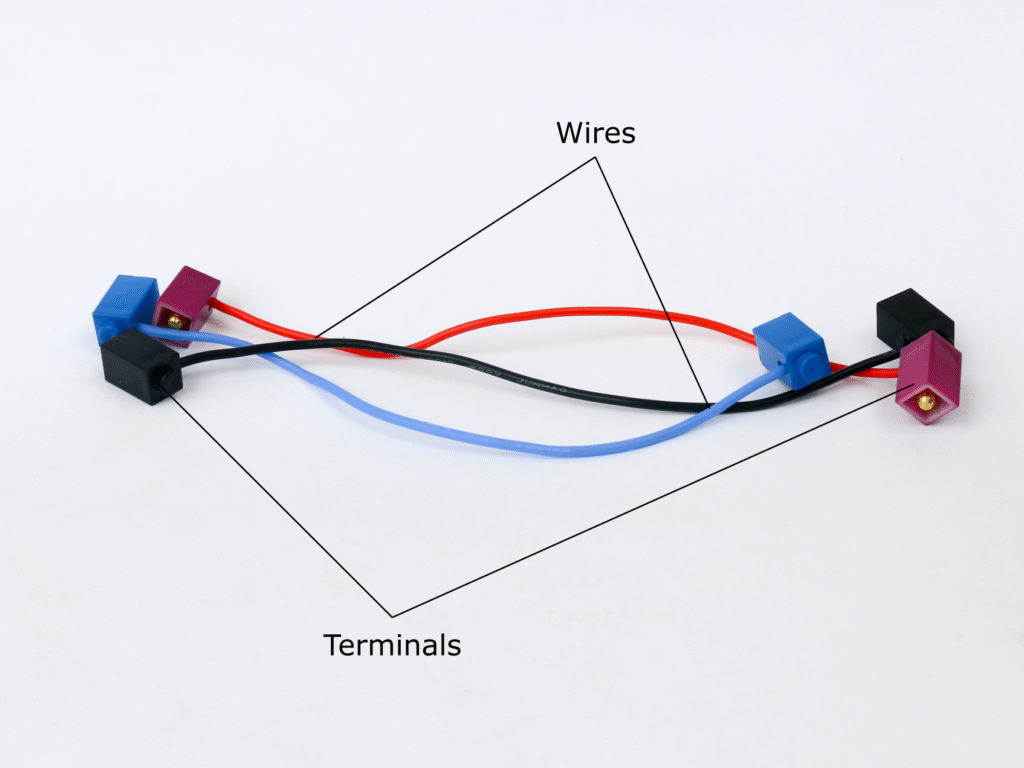
Connectors
Connectors are electrical wires with terminals at each end. These are used to connect two pins e.g. in order to power the microcontroller block using battery block, connectors are used to connect the “Vs” and ground pins of both the block respectively.
LED Blocks
LEDs are light emitting diodes which when powered in the right polarity emit light of different colors. The material used in the diode determines the color of light emitted by it. LED blocks are available with different colors like red, green, blue & white.
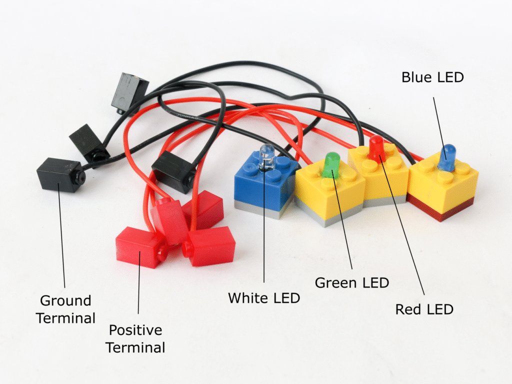
The LEDs are unidirectional device which means it has a positive and a negative terminal. The LED block positive terminal is red colored while negative terminal is black colored. The LED blocks have a resistor of value 220Ω built in. This resistor acts as current limiting device and hence an LED block can be directly connected to battery block or microcontroller digital I/O pins without needing any additional precautions.
RGB LED Block
RGB LED incorporates three differently colored LEDs, namely red, green & blue in a single package. By adjusting input voltage for each color LED, different colors can be generated according to color theory.
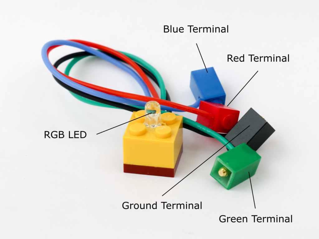
The RGB LED has 4 terminals; one each for red, green and blue light and a common ground colored in black. Like the LED block, the RGB LED also has built in resistors with 220Ω value, so the terminal can directly be connected to microcontroller or a battery block without any concern of damaging the LED.
Transistor Block
A transistor is a semiconductor device which can be used to control flow of current. A transistor has 3 pins; a base, an emitter & a collector. Voltage is applied across the emitter and collector. As long as the base pin is not provided any voltage there is no current flow between the emitter and the collector. If a small voltage is applied at the base pin, the transistor allows current flow between the emitter & collector. Hence it is called an electronic switch.
The transistor block uses TIP122 NPN Darlington transistor. Maximum current rating of the transistor is 3A. A 1KΩ resistor is built in at the base pin to control amount of current drawn by base pin so that it can be directly connected to microcontroller I/O pin. The color coding for the pins is as below.
Potentiometer Block
A potentiometer is a variable resistor device and acts as a voltage divider. A potentiometer has three terminals; supply, ground and output. By rotating the knob, voltage between the output terminal and ground can be adjusted between zero and supply voltage.
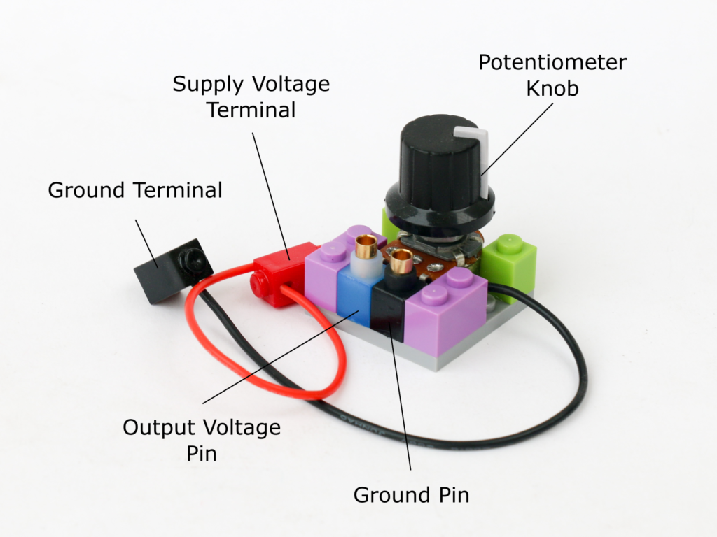
The potentiometer block has two terminals; red terminal for supply voltage which is typically 5V and black terminal for ground. The microcontroller also has two pins on the front, a blue pin & a black pin. Depending on the position of the knob, the voltage between the blue pin and the black pin varies between 0V and supply voltage. The voltage at blue pin increases as the knob is turned clockwise and decreases as it is turned anti-clockwise.
If the supply voltage is 5V at the red terminal, the blue pin can be connected to any of the microcontroller analog I/O pin to read the voltage. Potentiometer block is used as user input to adjust level to control output driven through the microcontroller block.
Photoresistor Block
A photoresistor, also know as light dependent resistor (LDR) is a semiconductor component that changes its resistance value depending on the ambient light. A photoresistor is made of a semiconductor material which typically does not conduct electricity. However when a light particle, called photon, is incident on it, it knocks and excites an electron making it available to conduct electricity. Higher the amount of incident photons, higher is conductivity of the photoresistor.
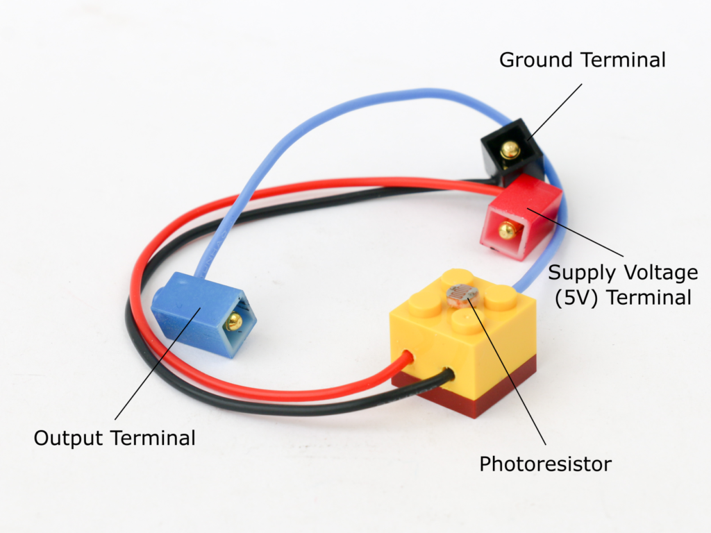
The photoresistor block has positive (red) terminal to connect to 5V and a negative (black) terminal to connect to ground. The blue terminal is for signal and is to be connected to analog I/O of the microcontroller.
The signal terminal is pulled down to ground using 10KΩ resistor which creates a voltage divider to allow creating voltage across positive and signal pin.
Buzzer Block
A buzzer creates a sound of certain frequency by vibrating a diaphragm inside it. The diaphragm is vibrated using an electromagnet supplied by an oscillating signal. An active buzzer has an inbuilt oscillator circuit so it only needs a supply voltage to create a sound.
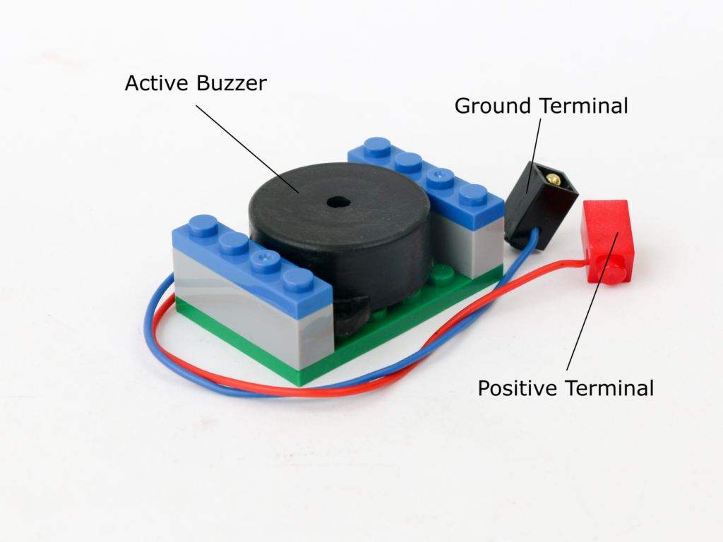
Buzzer block has a positive (red) and a negative (black) terminal. Positive terminal can be connected to battery 5V or microcontroller digital I/O pins. Negative terminal is connected to battery or microcontroller ground pin.
Speaker Block
A speaker, like a buzzer, creates sound by vibrating a diaphragm inside it by using an electromagnet in it. However unlike a buzzer, it does not have its own oscillator circuit built-in. It needs an external oscillating sinewave signal which can be generated by an oscillator. The speaker can also be used with square wave oscillations generated by a microcontroller.
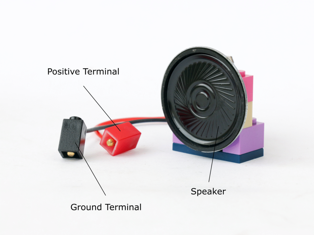
The speaker block uses an 8Ω 0.5W speaker. The speaker block has two terminals; positive (red) terminal to connect to an oscillating signal and black terminal for ground. If the speaker is driven directly by connecting it to microcontroller digital I/O pin, there is a risk of damaging the microcontroller board due to excess current draw. The sound level is also low when driven directly from microcontroller.
It is advised to use a transistor block to drive the speaker block which eliminates risk of damage and also increases sound volume. In this case, the base pin of transistor block is connected to digital I/O pin of microcontroller block. Collector pin of transistor block is connected to the 5V power supply on battery block. Speaker block positive terminal should be connected to the emitter pin of the transistor block and the speaker block ground terminal should be connected to battery block ground pins.
DC Motor Block
A DC motor consists of a rotor with copper winding housed in a permanent magnet housing. When a current is passed through the rotor winding, it creates a magnetic field which tries to align with the magnetic field for permanent magnet in the housing. As the shaft rotates, the direction of current in the rotor is reversed using a component called a commutator.
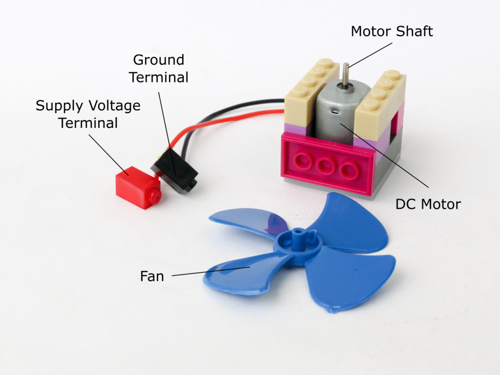
The DC motor block has a 3V to 6V brushed DC motor. It has two terminals, a red terminal and a black terminal, however since a dc motor is bi-directional the color of the terminals is only used as identifier to define the direction of rotation.
The DC motor can consume 350mA at no load and higher current with load. For this reason, never connect the motor directly to the microcontroller I/O pins. Use transistor block to trigger as well as control speed of the DC motor block. Connect the base pin of transistor block is to digital I/O pin of microcontroller block. Collector pin of transistor block is connected to the 5V power supply on battery block. One of the DC motor block terminal should be connected to the emitter pin of the transistor block and the other terminal of DC motor block should be connected to battery block ground pins.
When the digital pin provides HIGH to the transistor base pin, the DC motor runs at full speed. PWM signal can be used to control the speed of the motor.
The DC motor block comes with a fan which can be attached directly on the shaft of the motor. The DC motor block can be mounted vertically or horizontally using the building block connection.
Infrared Proximity Sensor Block
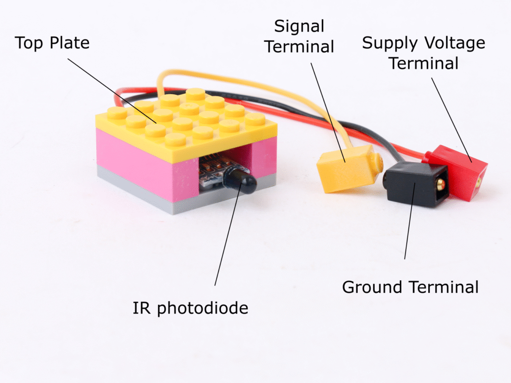
Infrared proximity sensor consists of an infrared LED and a photodiode. When an obstacle is placed near the sensor, the infrared light emitted by the IR LED is reflected back and is detected by the photodiode.
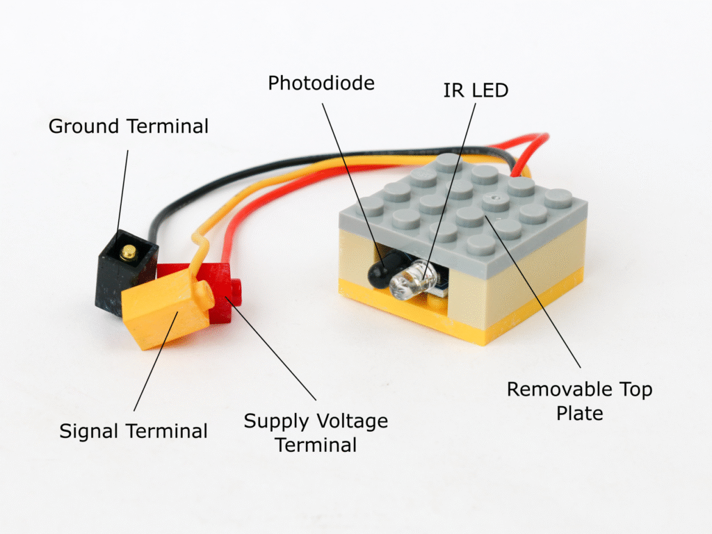
The IR proximity sensor block has 3 terminals. Red terminal for 5V supply voltage, black terminal for ground and a yellow terminal for digital signal which can be connected to microcontroller digital I/O pins. When an obstacle is detected, the signal output goes LOW. In the absence of obstacle, the signal output is HIGH.
The top plate of IR proximity sensor block can be removed to access a potentiometer. This potentiometer can be adjusted to adjust the sensitivity of the sensor.
Voltage Sensor Block
A voltage sensor consists of a voltage divider with 30KΩ & 7.5KΩ resistance in series. The source voltage is applied across the both resistors and output voltage is taken across 7.5KΩ resistor. By the formula of voltage divider, the output voltage is 7.5/(3+7.5) = 0.2 times the supply voltage. Hence the voltage sensor can measure voltage of any source upto 25V and convert it in the range of 0v to 5V.
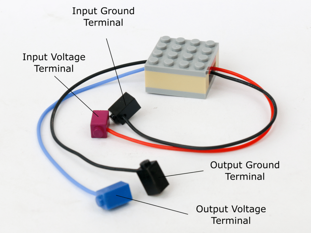
The voltage sensor block has two terminals as inputs and two terminals as outputs. The purple input terminal is to be connected to voltage source to be measured. Maximum voltage allowable to be measures is 25V. The black terminal on the side of input terminal is to be connected to voltage source ground.
The blue output terminal provides voltage between 0V to 5V and can be connected to microcontroller analog I/O pin. The black terminal on the output side to be connected to microcontroller ground pin.
Flame Sensor Block
Fire can be detected by light and heat emitted in infrared portion of light spectrum, specifically in the wavelength between 760nm to 1100nm. Similar to the infrared proximity sensor, the flame sensor has a photodiode which detects the infrared light indicating presence of fire.
Similar to IR proximity sensor, flame sensor block has 3 terminals. Red terminal for 5V supply voltage, black terminal for ground and a yellow terminal for digital signal which can be connected to microcontroller digital I/O pins. When fire is detected, the signal output goes LOW. In normal case, the signal output is HIGH.
The top plate of flame sensor block can be removed to access a potentiometer. This potentiometer can be adjusted to adjust the sensitivity of the sensor.
Motion Sensor Block
Motion can be sensed using a passive infrared (PIR) sensor. The sensor detects changes in infrared radiation arriving at the sensor and thus detecting the motion in its field of view.
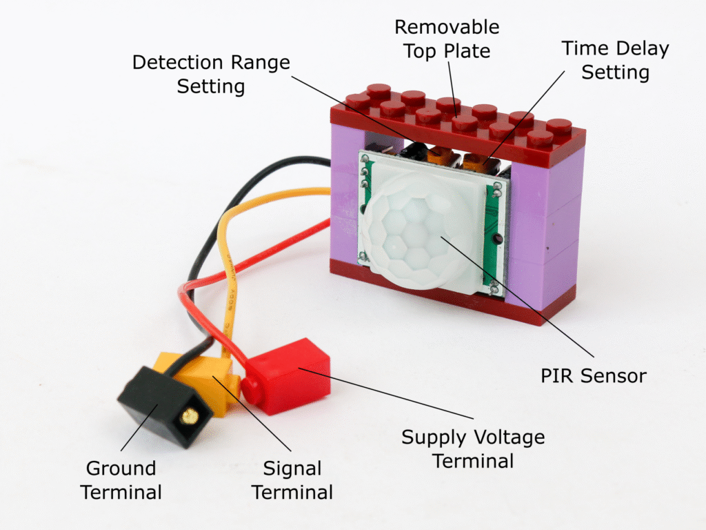
The motion sensor block contains HC-SR501 passive infrared (PIR) sensor. The motion sensor block has three terminals, red terminal to connect to 5V supply, black terminal to connect to ground and yellow terminal to connect to a microcontroller digital I/O pin.
When motion is detected, the signal in yellow terminal goes HIGH indicating motion. The signal remains HIGH as long as motion is detected.
The top plate of the sensor block can be removed to access two potentiometers. The left one to adjust time delay of the sensor and the right one to adjust the detection range. The time delay adjuster controls amount of time the signal to remain high once a motion is detected.
Sonar Block
SONAR stands for SOund NAvigation and Ranging. It works on a principle of echo. The sonar sensor has two ultrasonic transducers. One of the transducer emits ultrasonic sound pulses and the other listens for the reflected waves. Based on the time it takes between transmission and receipt, the distance to the reflective surface is calculated.
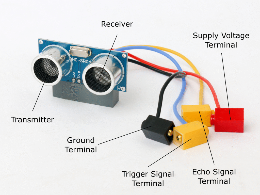
The sonar block uses HC-SR04 ultrasonic sensor. The sonar block has four terminals. Red terminal is for 5V source while black terminal is for ground. The yellow terminal with blue wire is the trigger signal terminal and yellow terminal with yellow wire is an echo signal terminal. Both of these are to be connected to microcontroller digital I/O pin. Note that the trigger signal terminal has to be connected to a digital I/O pin which is PWM capable e.g. D3, D5, D6, D9, D10 or D11 in order to be able to send pulses of the signal.
Temperature & Humidity Sensor Block
The temperature and humidity sensor can measure temperature and relative humidity of ambient environment.
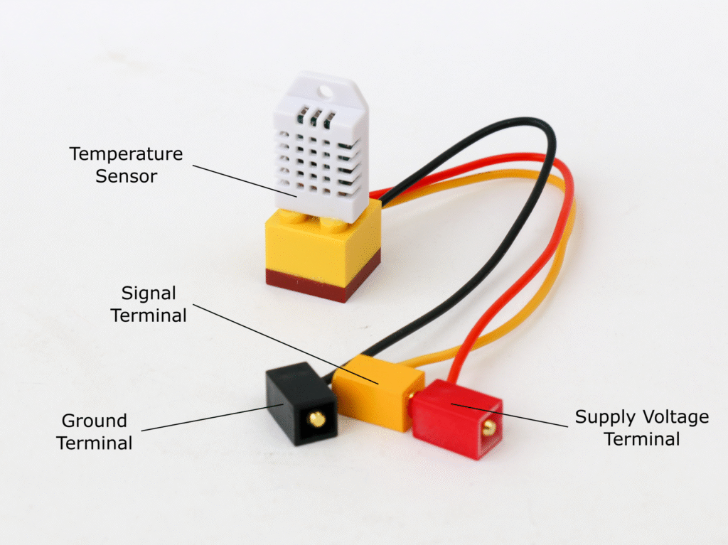
The temperature and humidity sensor block uses DHT-22 sensor. This sensor provides ambient temperature and relative humidity with accuracy of ±0.5°C and ±2% RH. The sensor has its own communication protocol which allows readings to be taken using a digital I/O pin. The frequency of reading is once every two seconds. The sensor has a built in 10KΩ pull up resistor for reliable signal.
The temperature and humidity sensor has three terminals. Red terminal to be connected to 5V supply, black terminal to be connected to ground and yellow terminal to be connected to microcontroller digital I/O pin.
LED Ring Block
The addressable LED ring has ability to activate an individual LED. These LED are RGB LEDs so each LED can be programmed to generate variety of colors. Addressable LED rings are available with different number of LED like 3, 8, 16 & 24. All the rings operate on same principle and hence can be used interchangeably.
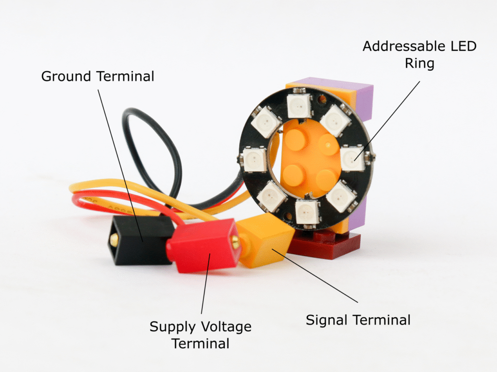
The LED ring block employs WS2812 addressable LED rings. The LED ring block has three terminals, red terminal to connect to 5V source, black terminal to ground and yellow terminal to digital I/O of microcontroller.
The signal is sent through yellow terminal to activate required LEDs in the rings with a required RGB color information. There is a built-in 1KΩ resistor at the input terminal so it can be directly connected to the digital I/O pin of microcontroller.
Each of the LED can consume upto 60mA, hence for an LED ring with 8 LEDs, the current consumption can go upto 480mA. For an LED ring with 16 LEDs, current consumption can be as high as 960mA. It is recommended to use battery block 5V supply pin instead of microcontroller 5V supply pin.
Servo Block
A servo is a motor and a positional sensor combined which can control motion precisely. A servo has a shaft on which a servo arm is attached. The rotational position of the servo arm is precisely controlled by providing a control signal to the servo.
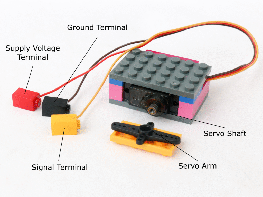
The servo block used MG-90S servo with 180° rotation. The servo block has three terminals; red terminal for 5V voltage supply, black terminal for ground and the yellow terminal for pulsed signal which can be connected to microcontroller block digital I/O pins.
The servo might draw upto 250mA of current while operating, however the current draw may rise upto 800mA when it is stalled. It is recommended to use battery block 5V power supply to drive the servo rather than microcontroller block 5V power.
Sound Sensor
A sound sensor simply detects and converts incoming sound signal to electrical signal. It consists of a microphone and an amplifier circuit to be able to use that signal to process.
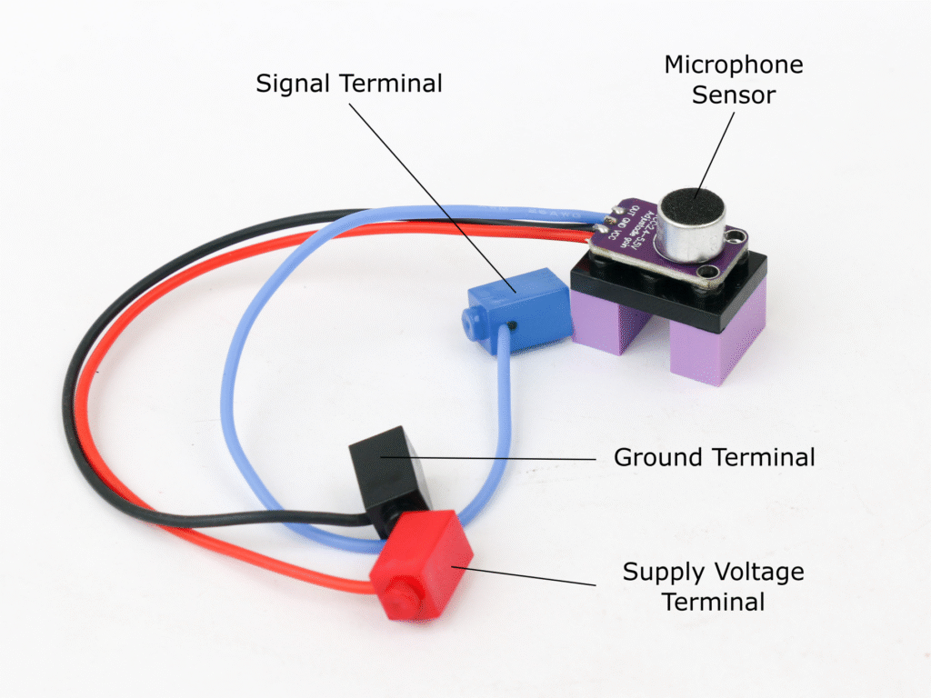
The sound sensor block uses MAX4466 microphone amplifier board. The sound sensor has three terminals; red terminal for 5V power supply, black terminal for ground and the blue terminal for the signal generated by the sensor. The blue terminal can be connected to microcontroller analog I/O pins to read the sensor.