Getting Started
Congrats on getting your own Makernova Robotics Kit. The Makernova Robotics kits come with variety of sensor blocks, actuator blocks, microcontroller blocks and battery blocks. You can check out documentation for all the blocks in the Learn section. In this section, we will start the learning journey with the kit.
We will start with some basic projects to get familiar with different blocks in the kit. We are working on electrical circuits, which can be a fire hazard if not used properly. Always get an adult to supervise when working with Makernova kits.
Simple LED Circuit
An electric circuit a closed path which allows electricity to flow. An electric circuit requires a power source which provides a voltage difference across its terminals, a load which is an equipment that consumes electricity to create useful work and connecting wires to create a closed loop. A typical electrical circuit is shown below.


DO NOT CONNECT THE POSITIVE AND NEGATIVE PINS OF THE BATTERY DIRECTLY TO EACH OTHER. EXCESSIVE CURRENT FLOW MAY RESULT IN FIRE HAZARD.
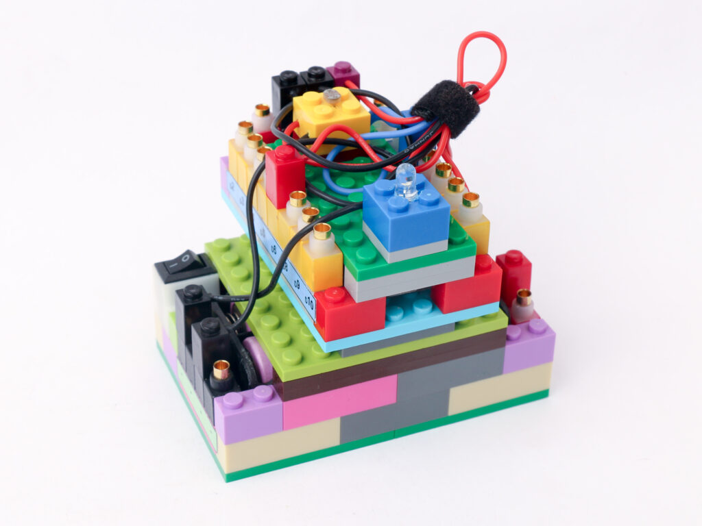
In the first project, we will use a battery block as a power source and an LED block as a load. You can use any color LED block for this project. Connect the red terminal of an LED block to the red pin of the battery block. The red pin of the battery block provides positive 5 volts supply. Connect the black terminal of the LED block to the black pin of the battery block. The black pin represents negative terminal. Turn the power on by using the switch on the battery block.
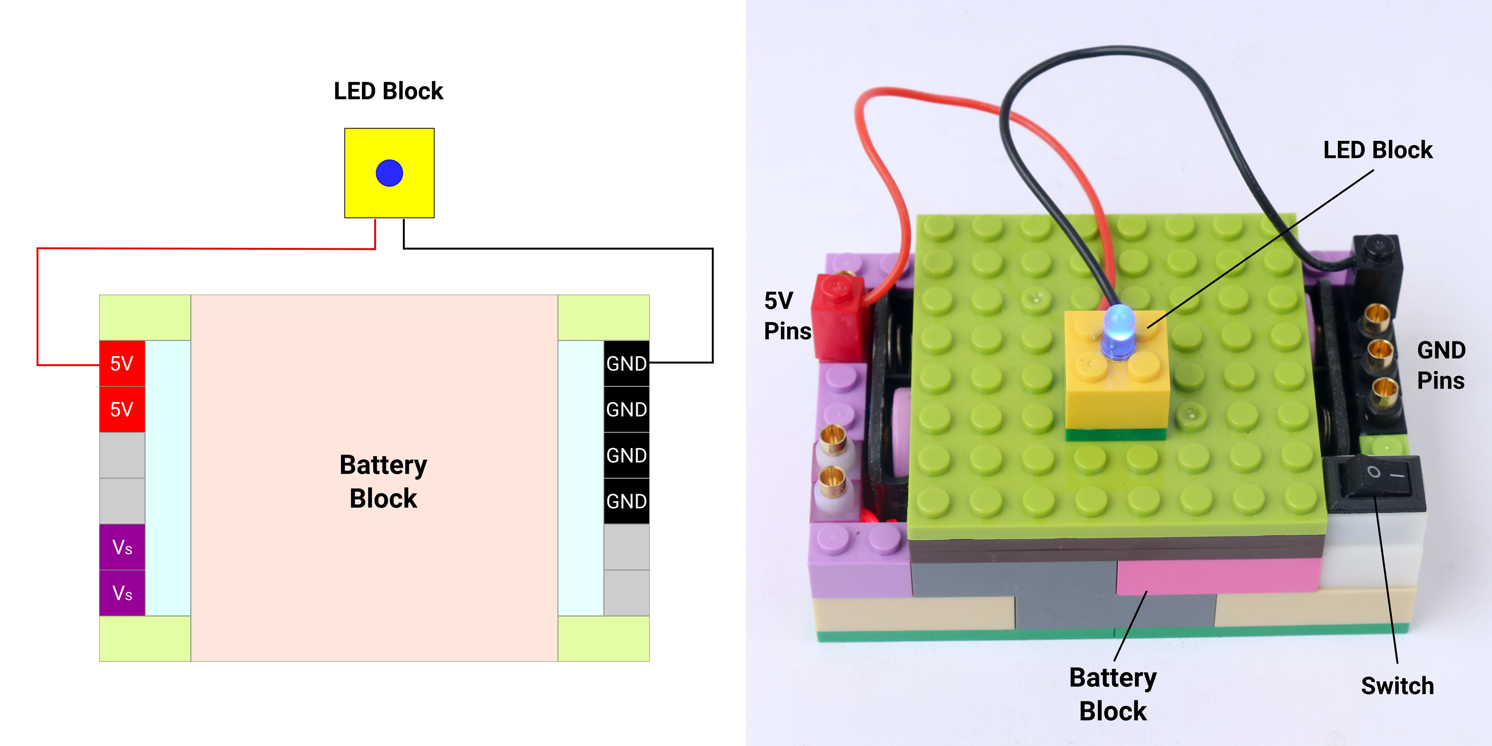
Electric current passes through the LED block causing the LED to light up. LED is a uni-directional component which means if the terminals are switched in a way that red terminal connected to black pin and black terminal to red pin, electric current will not pass and hence LED will not light up.
You can check out fundamental theory of the electricity and some simple electrical circuits in the following YouTube video.
DC Fan Circuit
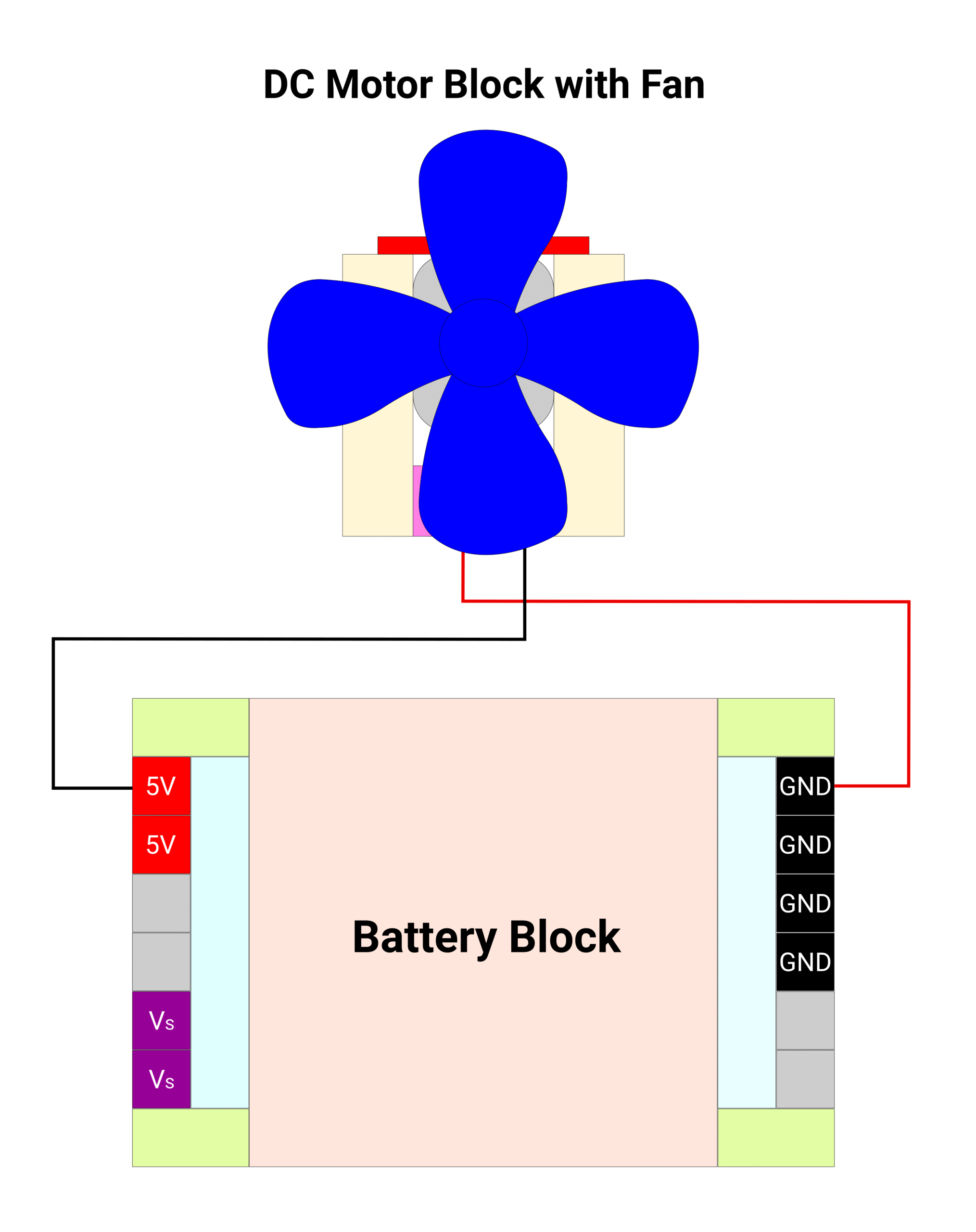
Similar to the previous LED circuit, we can power up a DC motor block using the battery block. When voltage is applied across a DC motor, it creates rotational motion on its shaft. If a fan is attached to the shaft of the DC motor, the fan will blow air. Connect the red terminal of the battery block to the red pin of the battery block. Connect the black terminal of the battery block to the black pin of the battery block. Turn on the power supply by the switch and observe the direction of rotation of the fan. Depending on the direction of rotation. the fan will blow air forward or backward.
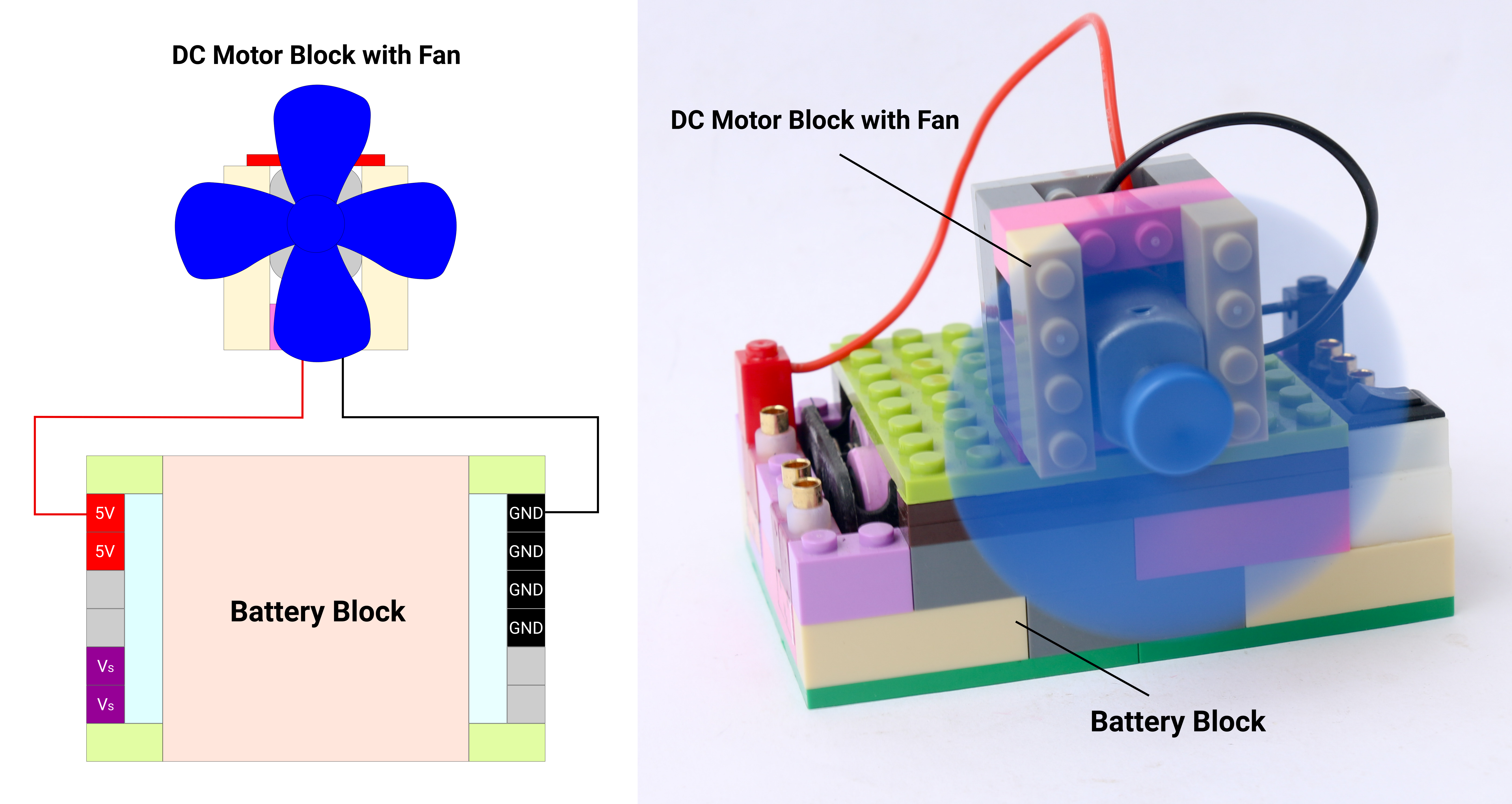
Now switch the direction of electric current by reversing the connections. Connect the red terminal of the DC motor block to the black pin of the battery block and black terminal of the DC motor block to the red pin of battery block. You can observe the direction of rotation of shaft and hence direction of air flow is reversed.
LED Brightness Control
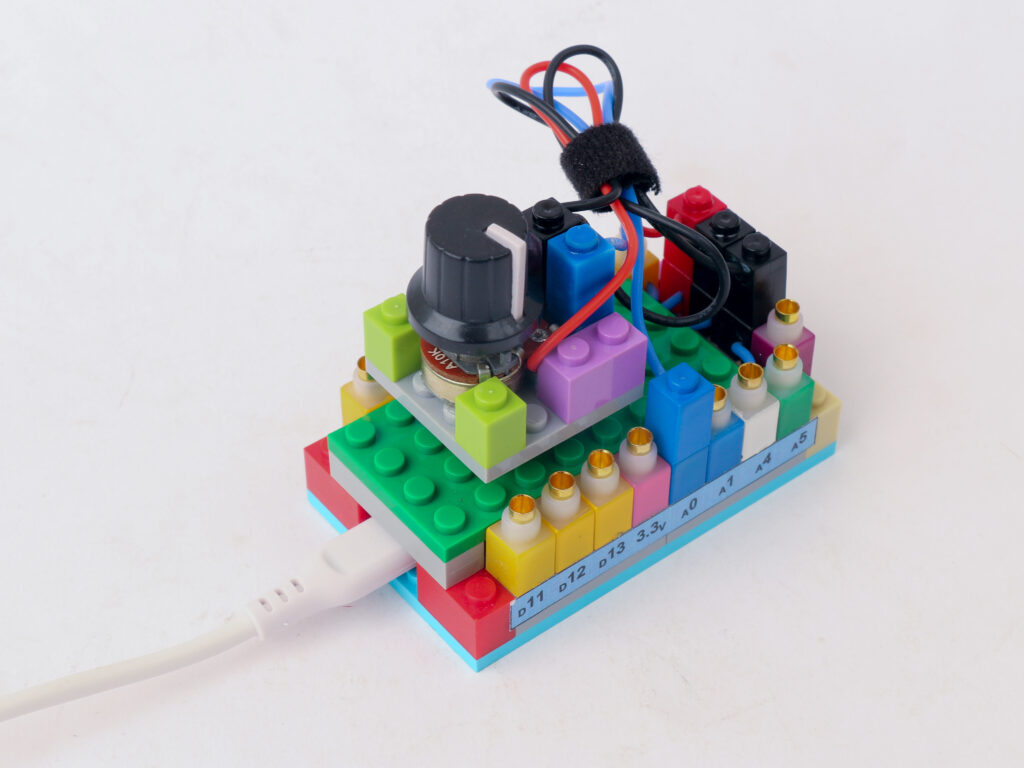
A potentiometer is a variable resistor device. The resistance can be changed by turning the knob which acts like a voltage divider. Using the potentiometer block, we can vary the voltage given to the LED block which changes the light intensity accordingly. Connect The red terminal of the potentiometer block to the red 5V pin of the battery block. Connect the black terminal of the potentiometer block to the black “-” pin of the battery block.
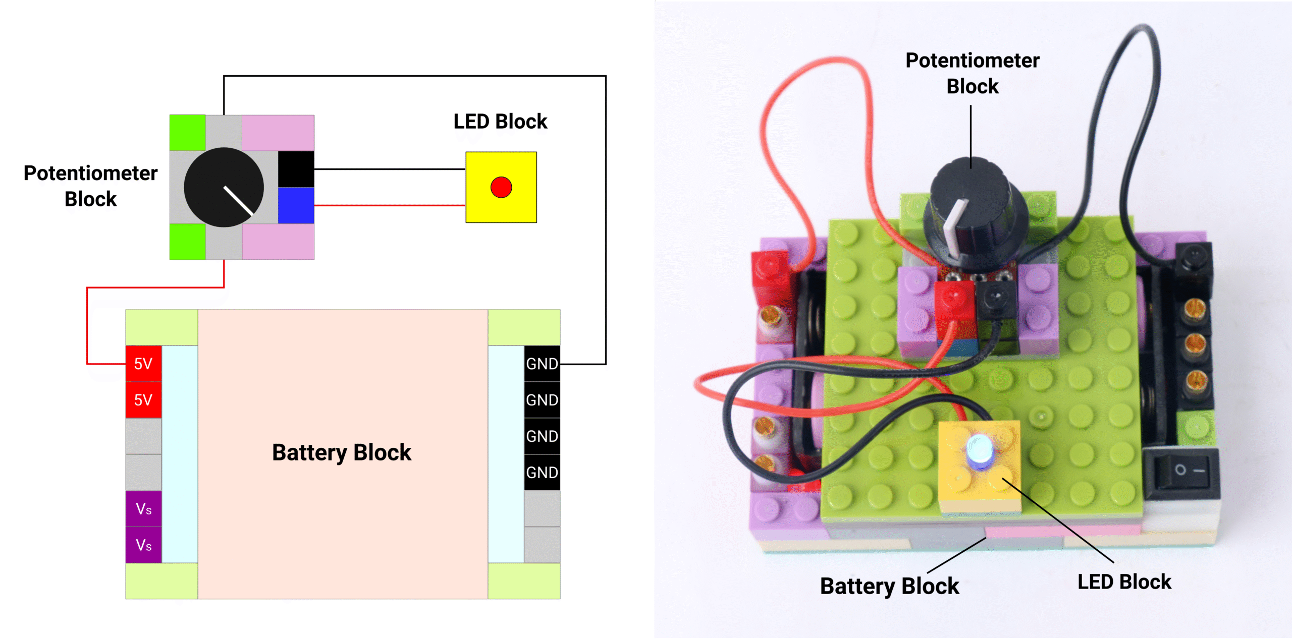
Connect the red terminal of LED block to the blue pin of the potentiometer block and connect the black terminal of the LED block to the black pin of the potentiometer block. Power on the supply by the switch on the battery block. Rotate the knob on the potentiometer block and observe the change in LED light intensity.
Buzzer Volume Control
Buzzer is a component that creates sound when supplied with voltage. Buzzer has internal oscillator circuit which creates oscillating signal. This signal actuates an electromagnet which vibrates a diaphragm accordingly.
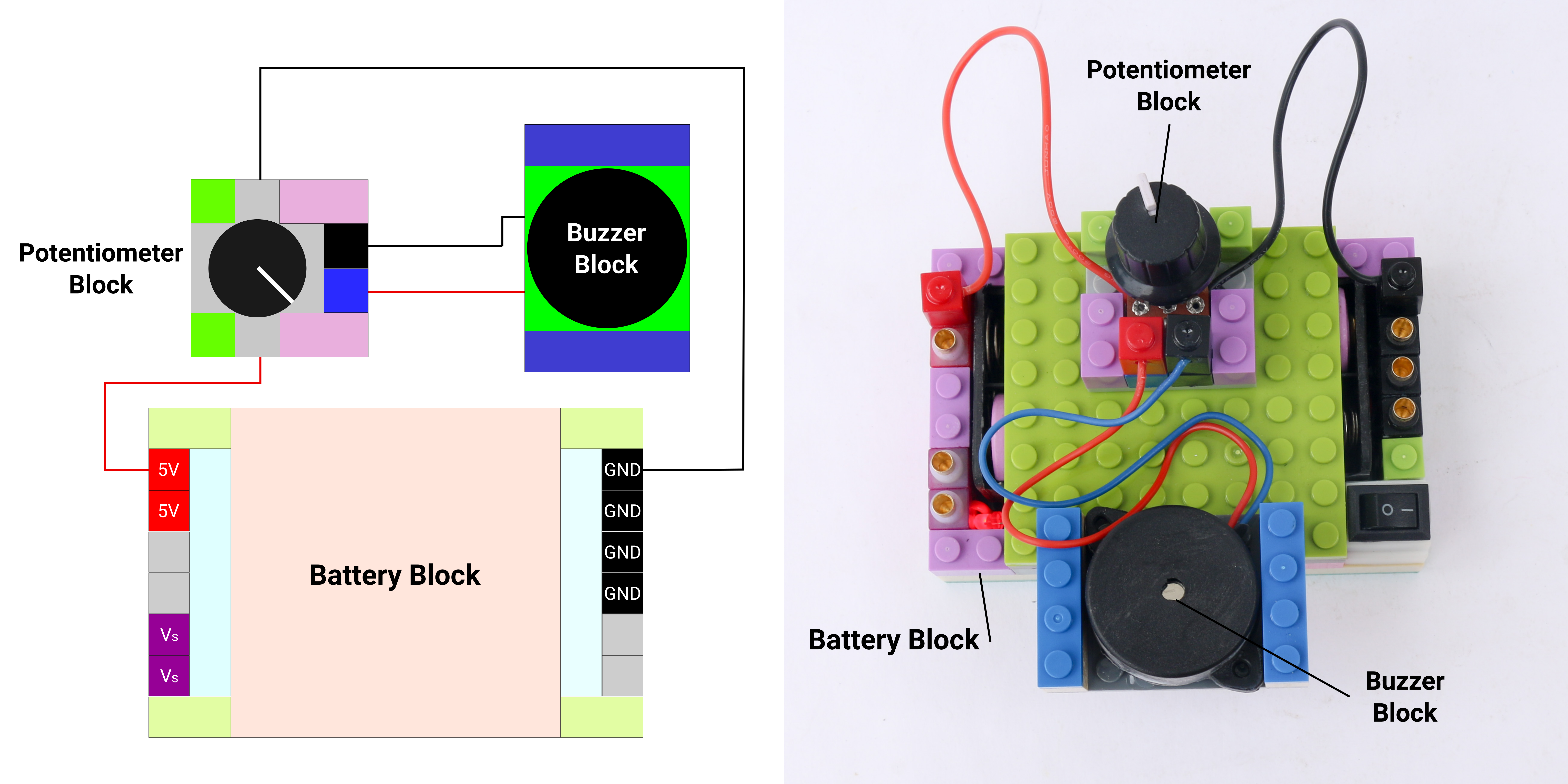
Similar to LED intensity control, we can control volume of the sound created by buzzer block by using a potentiometer block. Make the same connections as LED intensity control except that instead of LED block connect the buzzer block. Connect the red terminal of buzzer block to the blue pin of the potentiometer block and connect the black terminal of the buzzer block to the black pin of the potentiometer block.
Starting with Microcontroller
Microcontroller is a small computer that can be programmed to perform operations. Check out the fundamentals of a microcontroller in the Learn section. We can program a microcontroller using an app called IDE (Integrated Development Environment). Download Arduino IDE from official website.
Introduction to Arduino Sketch
A program in an Arduino IDE is called a “sketch”. We can think of 4 elements that forms a sketch
- First element is to declare variables, assign I/O pins, add libraries
- Second element is a setup function which runs only once when microcontroller is powered on. This section is used to initiate communication, declare I/O pins as inputs or outputs, initiate libraries etc.
- Third element is a loop function which runs continuously as long as the microcontroller is powered on. This is where the execution of the program is located.
- Fourth element is for user defined functions which can help to simplify execution in the loop function. These are not necessarily needed for all the sketches.
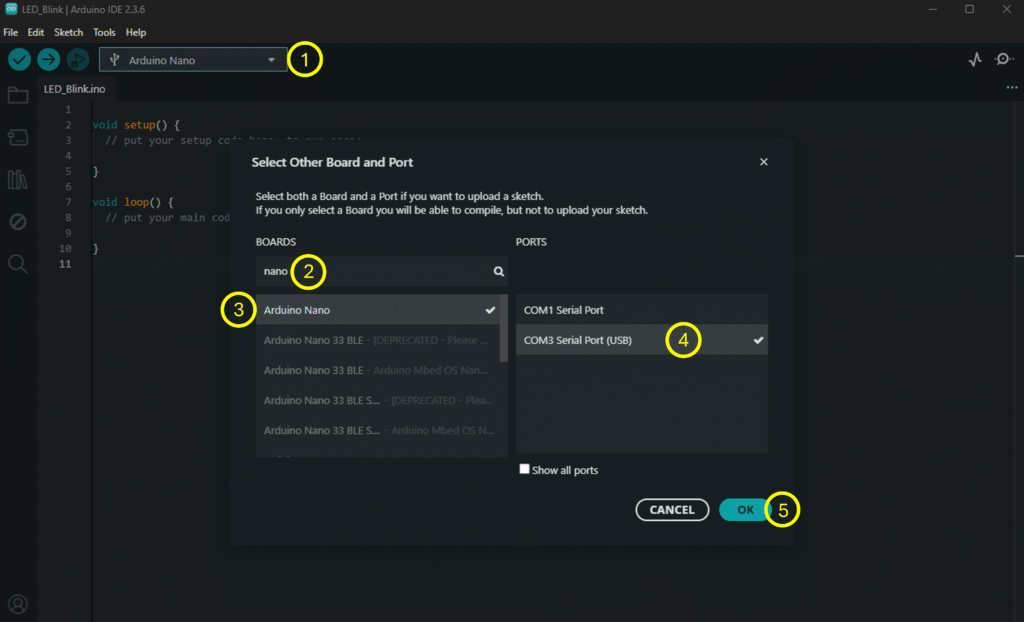
A snapshot of a new sketch in Arduino IDE looks like below. Please select the board as Arduino Nano from the board selection dropdown window for all the projects using Makernova microcontroller block.

LED Blinking using Microcontroller
In this project we will start our journey with microcontroller based control. we are going to build a simple setup to make an LED blink on and off with time period defined by us. let us look at the components we need to use.
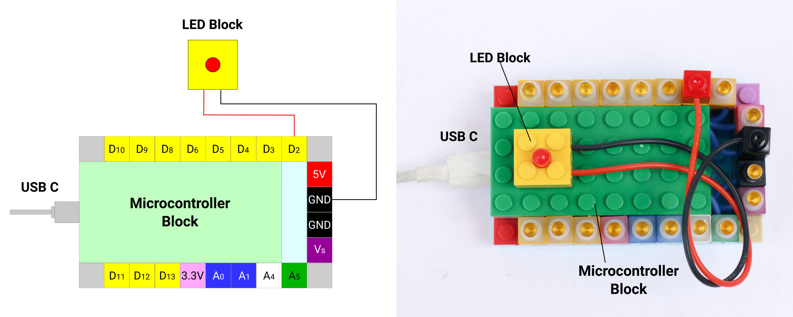
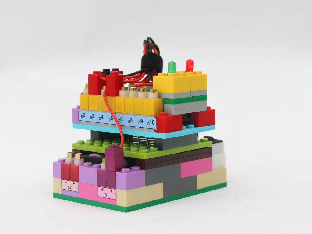
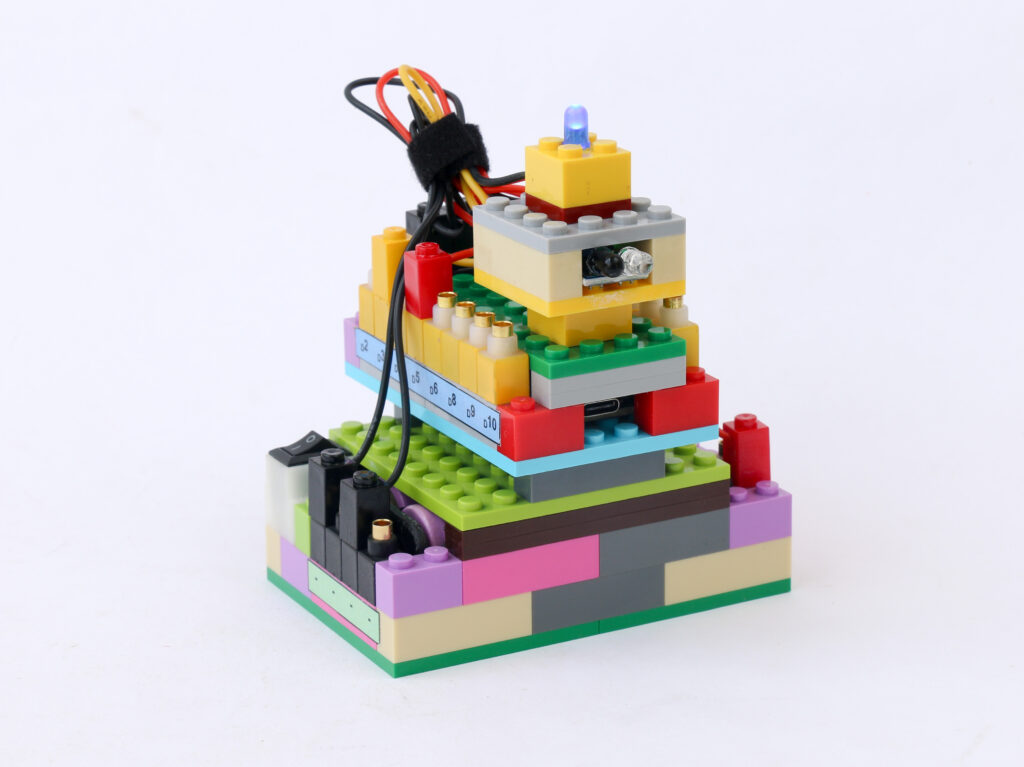
We need a microcontroller block which houses a Arduino Nano microcontroller. We also need an LED block which we will make blink. You can select any color LED block for this project. In order to power the microcontroller an an LED, we will need a battery block. We need connectors to connect power and ground pins of the microcontroller and the battery block. Lastly we need USB to USB-C cable to upload a program from computer to the microcontroller block.
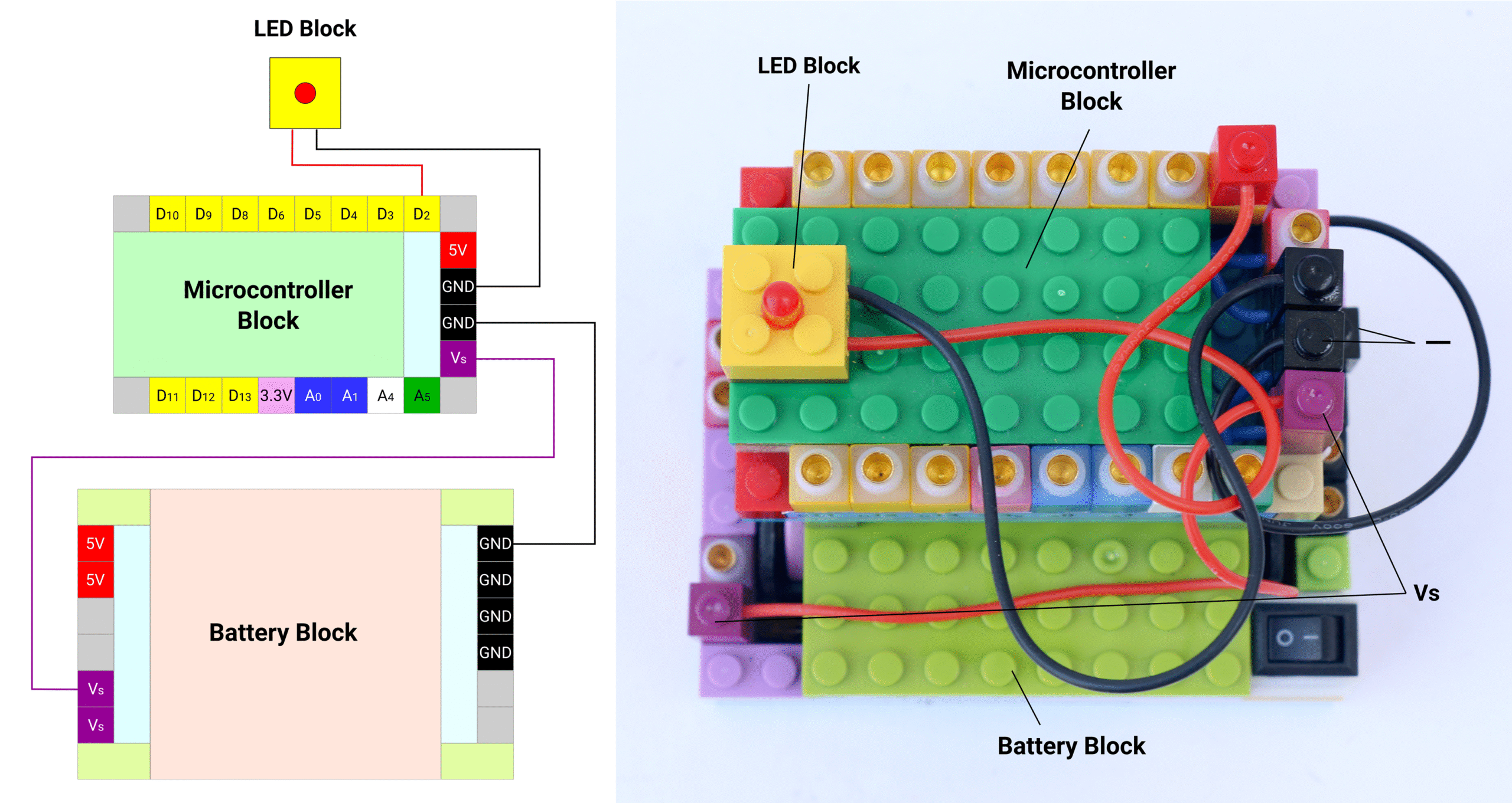
Microcontroller block has multiple pins. The pins labelled starting with D like D2, D3, D4 etc. are digital input output pins. These pins can read or supply electrical signal only on 2 levels which is 0V or 5V. We will use one of the digital I/O pins to drive an LED block, say pin D2. Connect the red terminal of the LED block to the pin D2. Connect the black terminal of the LED block to black pin on the microcontroller block which is labelled “-“. Connect USB-C cable to the microcontroller block and connect the other end to USB port of a computer.
Now let’s program the microcontroller block with Arduino IDE on a computer. Open Arduino IDE and start a new sketch. At the start, we need to select the microcontroller we have connected. Type Nano in the search bar and select Arduino Nano with appropriate USB port.
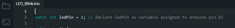
Once the board is selected, we can start writing the sketch in the sketch editor section. Firstly, we will need to declare the Arduino pin we are going to use to drive LED. In our case, we have used pin D2 so we will need to declare the same in the program. We will create a variable called ledPin and assign it as Arduino pin D2. Since the pin name is an integer we declare it as int. Also since the value of this variable will not change during execution, we will declare it as const int. We can add comments in the code to help us identify later on what is the purpose of that specific command. These comments are put after double forward slash like //. Anything after // is ignored by the compiler so it is not part of the executable steps.
The setup section is under the void setup section. In this section we will declare the pin ledPin as an output. This means the pin assigned to ledPin will supply signal and not read the signal. We declare this by using command called pinMode() as below.
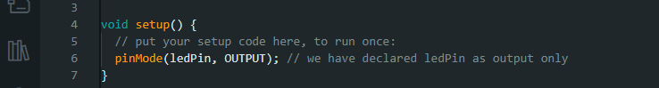
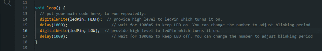
The execution happens in the void loop section. In this section, we will turn the LED on by providing high signal, wait for a second then turn the LED off by providing low signal and wait for another one second. These instructions will happen continuously in a loop, as long as the microcontroller is powered on. We will use command digitalWrite() to provide high or low signal to LED. We will keep the LED state as it is for a second using delay() command. The delay command stops the execution of the program for number of milliseconds as mentioned in delay command. Since we want to wait 1 second after we turn the LED on and off, we will put delay(1000) which is 1000mS = 1S.
You can copy entire program from below in to the Arduino IDE sketch editor.
/*
 First microcontroller program to blink LED. Connect LED block red terminal to pin D2
 Makernova Robotics @2025
*/
const int ledPin = 2;  // declare ledPin as variable assigned to arduino pin D2

void setup() {
  // put your setup code here, to run once:
  pinMode(ledPin, OUTPUT);  // we have declared ledPin as output only
}

void loop() {
  // put your main code here, to run repeatedly:
  digitalWrite(ledPin, OUTPUT);  // provide high level to ledPin which turns it on.
  delay(1000);                   // wait for 1000mS to keep LED on. You can change the number to adjust blinking period
  digitalWrite(ledPin, OUTPUT);  // provide high level to ledPin which turns it on.
  delay(1000);                   // wait for 1000mS to keep LED off. You can change the number to adjust blinking period
}
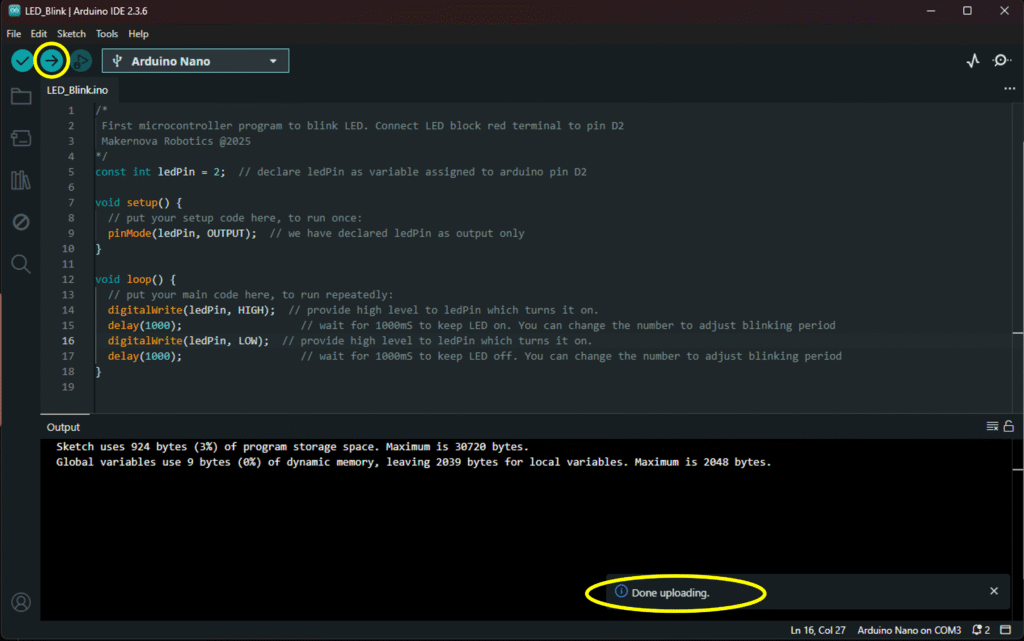
Once the entire sketch is ready, press upload button on top left portion of the IDE window. If there are any errors, it will show it in the output window. If there are no errors and the program is uploaded successfully, it shows message on bottom right accordingly.
Making a standalone project
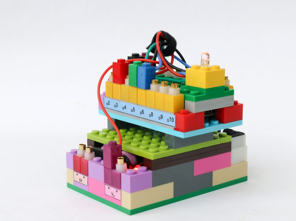
The microcontroller is powered by USB cable so as long as the microcontroller block is connected to the computer via USB, the LED will continue blinking. However, as soon as the USB cable is removed, the power supply to the microcontroller is stopped. We can use battery block to operate the blinking LED as a standalone project.
Connect the purple Vs pin on the microcontroller block to the purple Vs pin on the battery block using a purple connector. Similarly, connect the remaining black – pin on the microcontroller to any of the black – pin on the battery block. When power is switched on from battery block using the rocker switch, the LED will start blinking as programmed.
Congratulations!!! You have now finished your first robotics project. Continue your robotics journey by creating variety of projects with different sensors & actuators. Check out the projects cookbook for ideas.
Suggested Starter Projects
Traffic Lights: Make red & green traffic signal with LEDs
Learn providing digital signal output from microcontroller
Touchless Switch: Make touchless switch using proximity sensor
Learn to read digital signal input to microcontroller
Rainbow Light: Create full spectrum of colors using RGB LED
Learn to create analog signal output from microcontroller
Potentiometer Sensing: Read potentiometer position & display on computer
Learn to read analog signal input to microcontroller
Auto Sensing Light: Make light that automatically turns on when it gets dark
Learn to integrate input signal from sensor and generate output signal to drive actuator