Analog Input with Potentiometer
In this project, we are going to learn to read analog signal using the microcontroller. This is helpful in other projects which require to integrate an analog sensor, like a photoresistor, with the microcontroller.
Since the microcontrollers work on digital logic only which is a binary level, reading an analog signal requires conversion of incoming signal to digital signal. The process of converting an analog signal to digital signal is shown below.
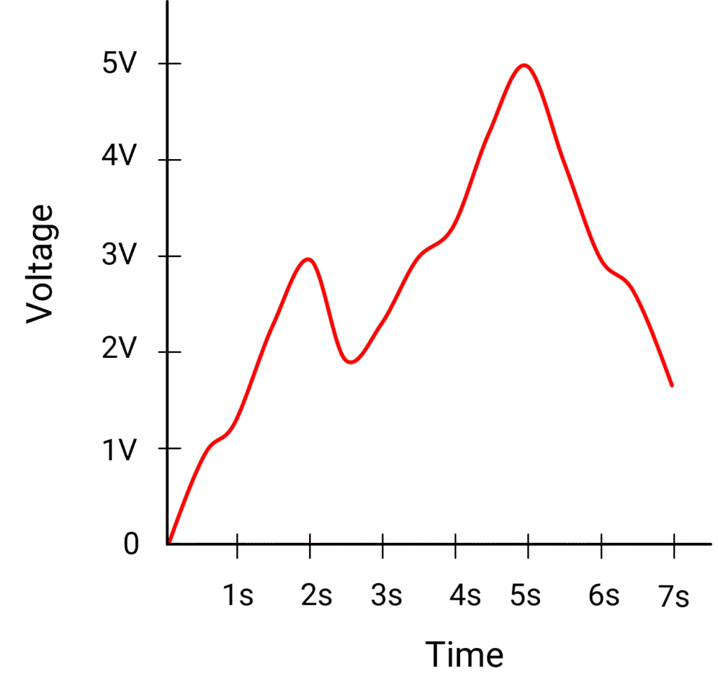
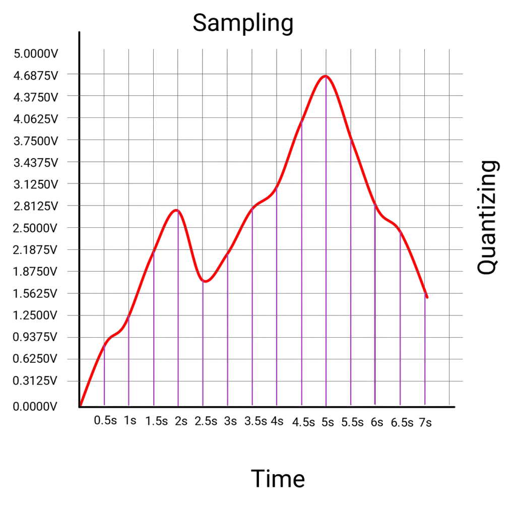
The analog signal is quantized in small steps. Each small step represents a digital level to which the signal is approximated to. In the above example, the analog signal between 0V to 5V is quantized in 16 levels, which means each level is 5/16 = 0.3125V.
The signal is then read at particular interval, called sampling. In above example, the signal is sampled at every 0.5 seconds. Each sampled reading is then approximated to nearest quantized step. so if the reading at 0.5 seconds is 0.85V, it is rounded to nearest step which is 0.9375V. At 1 second, the reading is 1.24V which is rounded to 1.25V. It is also called resolution of the conversion.
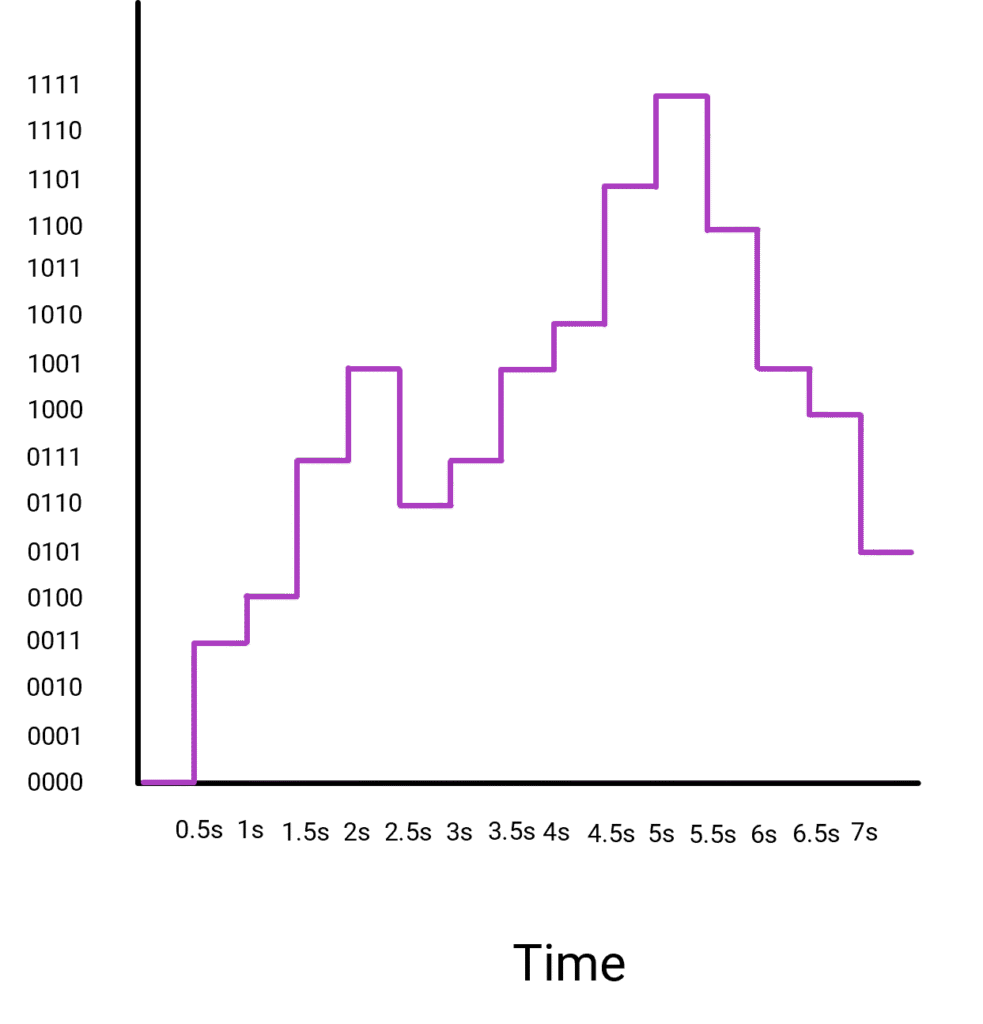
Since we quantized the data in 16 steps, we can denote each of the steps with a 4 digit binary number. With 4 binary digits, we get 2x2x2x2 = 24 = 16 combinations. The scale can then be represented in binary numbers with 0V represented as 0000 and 5V represented as 1111. The value of digital signal being the closest quantized value at every sampled time.
As you can see, the higher resolution of conversion, lower the error between analog value and the digital value. The resolution is represented in powers of 2. In the above example, we used 24 levels hence it was 4 bit conversion.
The sampling also makes impact on accuracy of the conversion. The more dynamic the data, more is the sampling frequency needed.
The electronic circuitry designed to perform the analog to digital conversion is called Analog to Digital Converter or ADC. The Arduino microcontroller in the microcontroller block has a built-in 10 bit ADC. This means the analog signal between 0V to 5V is quantized in 210 = 1024 levels.
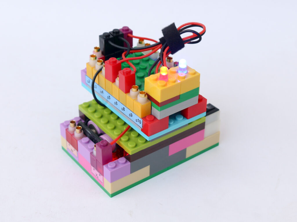
A potentiometer is a variable resistor device. As the know is rotated, the resistance value between its arm and ground varies. Due to this a potentiometer acts as a voltage divider. We can use the microcontroller to read the voltage at this variable resistance arm as analog signal.
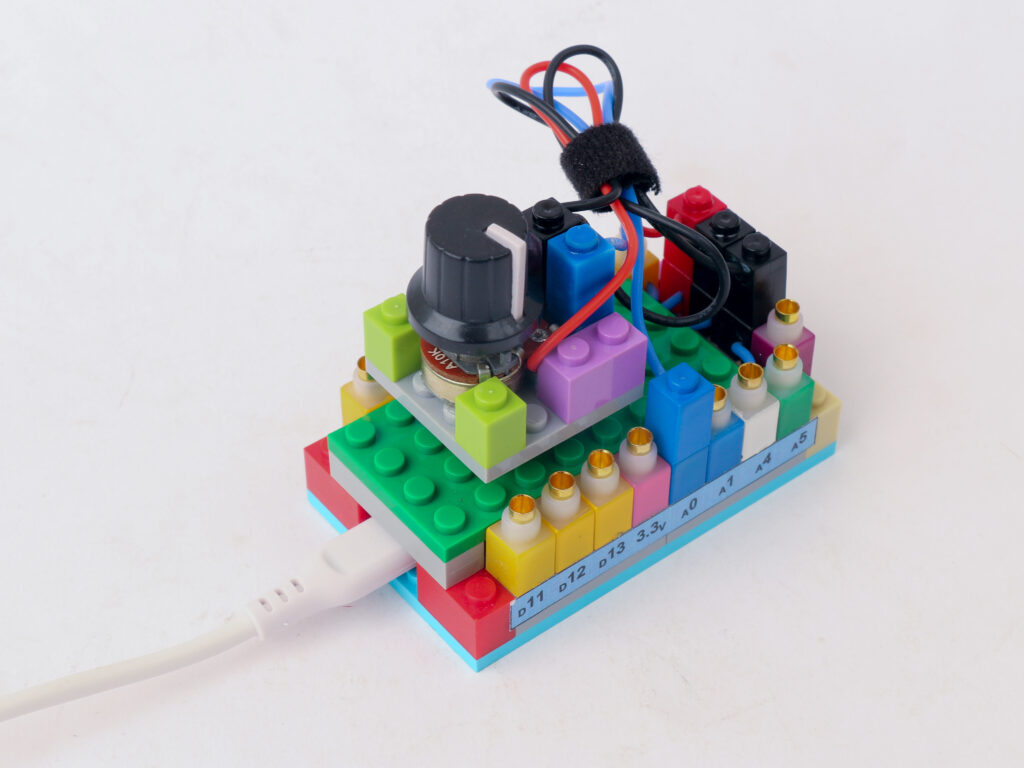
Components
Connections
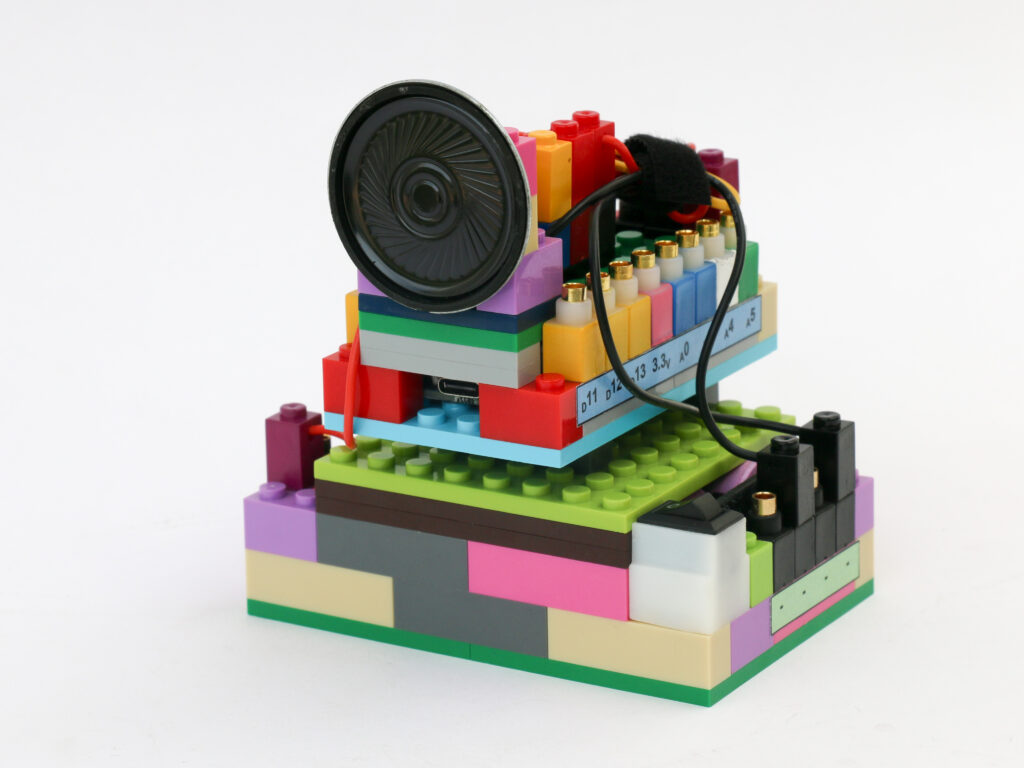
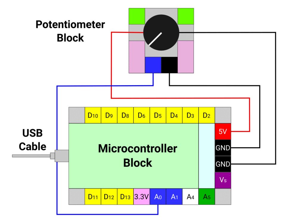
Connect the red and black terminal of the potentiometer block to the 5V (red) and ground (black) pins of the microcontroller block respectively.
Connect the blue pin of the potentiometer block to the A0 pin of microcontroller block with a blue connector. Connect the black pin of the potentiometer block and the ground pin of the microcontroller block with a black connector.
Connect the computer with the microcontroller block with USB cable and leave it be.
Code
We are going to use serial communication to communicate with the computer and display the input reading from the potentiometer. The rate at which the communication happens is called baud rate. We will use the smallest baud rate which is 9600.
/*
   Makernova Robotics 2025
   In this program we use a potentiometer to read analog value
   We will also use serial monitor to display the reading
*/

const int potPin = A0;  // declare A0 as pin to read potentiometer

void setup() {
  // initializing serial communication with computer
  Serial.begin(9600);  // 9600 is a baud rate. Use the same value in serial monitor
  // Initializing the potPin using pinMode(potPin, INPUT) is not required
}

void loop() {
  //read value of potentiometer in variable potValue
  int potValue = analogRead(potPin);
  // The value is read on scale 0 to 1023.
  // 0V is read as 0. 5V is read as 1023. Intermediate voltages are between 0 and 1023
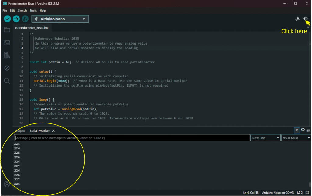
Once the code is written and uploaded, open the serial monitor window in the IDE by clicking on the symbol on top right. It opens up the serial window at the bottom showing the values of reading as shown below.