LED Brightness Control
In this project we are going to implement two concepts; analog sensing of voltage from potentiometer and PWM signal output to control LED brightness.
Analog sensing using microcontroller Analog to Digital Converter is discussed in more details on project about reading potentiometer signal. Similarly digital to analog conversion using PWM signal can be referred in the microcontroller block section in the Learn page.
The analog to digital conversion is 10 bit which means the input signal is in the range of o to 1023. While the PWM digital to analog conversion is 8 bit which means we can generate 256 voltage levels between 0V and 5V.
We will use map function in Arduino to be able to use 10 bit input signal and provide 8 bit output.
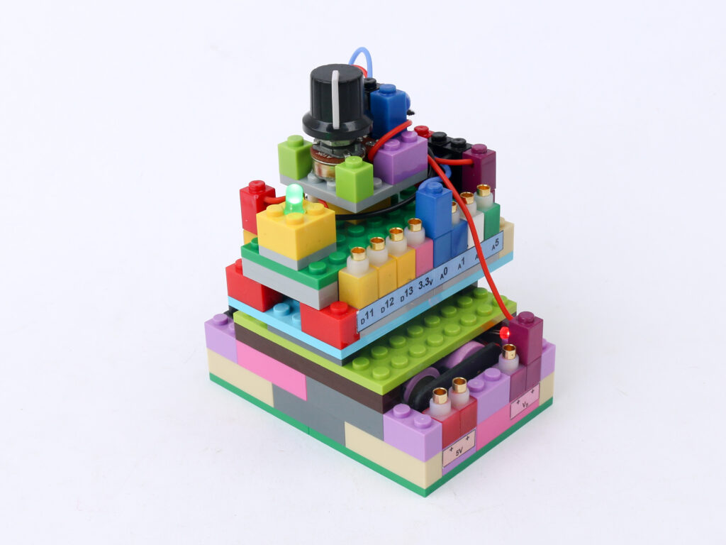
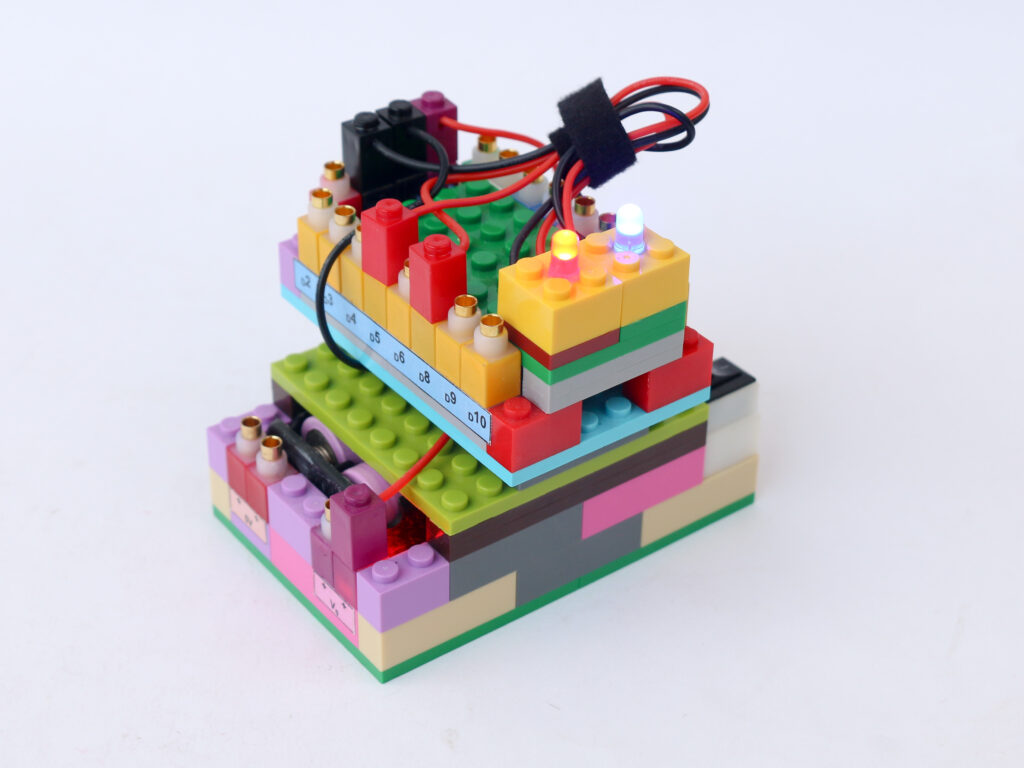
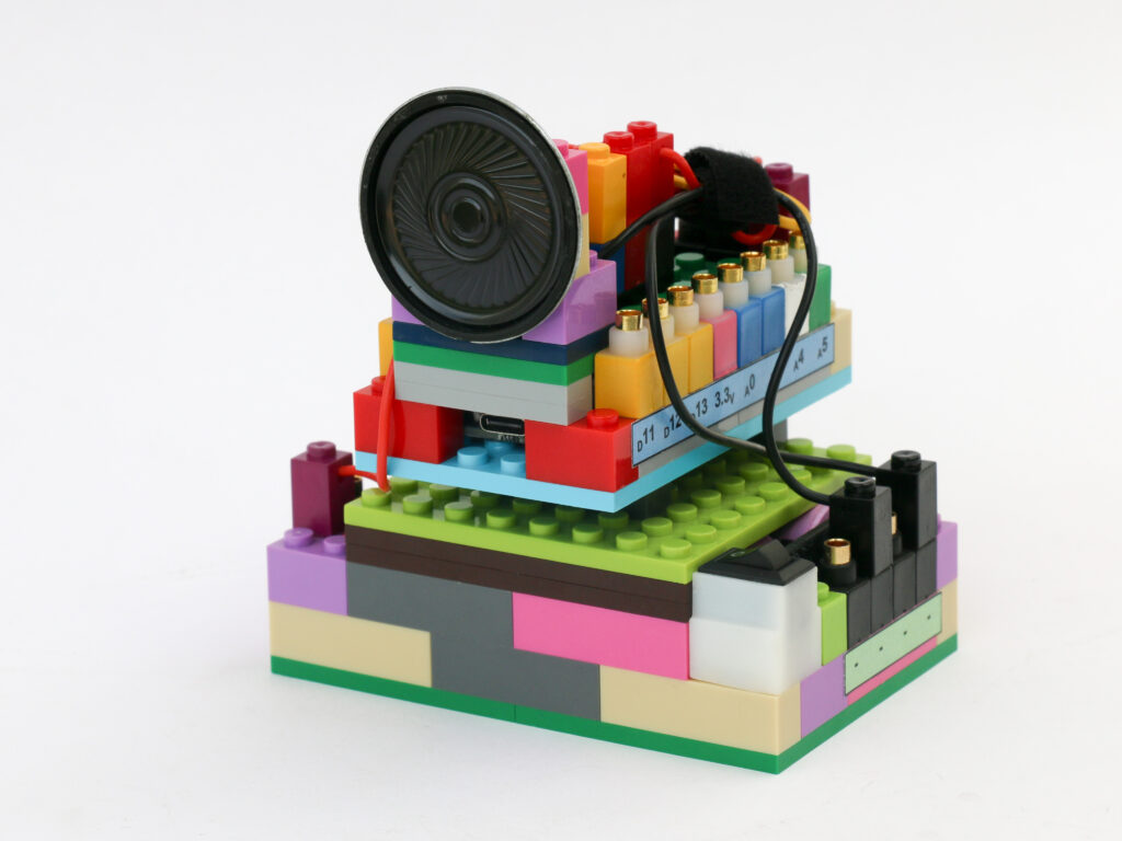
Components
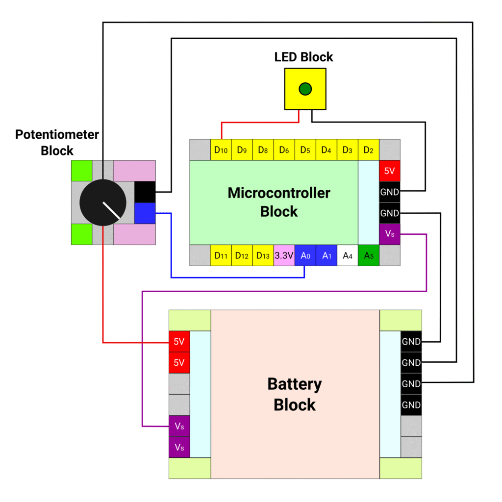
Connections
Connect the battery block Vs pin to the Vs pin of the microcontroller block. Connect any of black (negative) pins on the battery block to one of the negative (black) pin on the microcontroller block.
Connect the red terminal of the LED block to the microcontroller pin D10. Connect the black terminal of the LED block to the negative (black) pin of battery block.
Connect the red and black terminal of the potentiometer block to the 5V (red) and ground (black) pins of the microcontroller block respectively.
Connect the blue pin of the potentiometer block to the A0 pin of microcontroller block with a blue connector. Connect the black pin of the potentiometer block and the ground pin of the microcontroller block with a black connector.
Code
/*
   Makernova Robotics 2025
   In this program we use a potentiometer to read analog value
   and adjust LED intensity with help of PWM signal
*/

const int potPin = A0;  // declare A0 as pin to read potentiometer
// The pin to drive LED needs PWM capabilities so select only pins 3, 5, 6, 9 , 10 or 11
const int ledPin = 10;  // declare D10 as LED pin.


void setup() {
  // initializing serial communication with computer
  Serial.begin(9600);  // 9600 is a baud rate. Use the same value in serial monitor
  // Initializing the potPin using pinMode(potPin, INPUT) is not required
  pinMode(ledPin, OUTPUT);  // define LED pin as output
}

void loop() {
  //read value of potentiometer in variable potValue
  int potValue = analogRead(potPin);
  // The value is read on scale 0 to 1023.
  // 0V is read as 0. 5V is read as 1023. Intermediate voltages are between 0 and 1023

  // Arduino 8 bit value to convert digital to analog signal using PWM
  // 0 means 0% duty cycle, 255 means 100% duty cycle
  // we use map function to scale down the readings between 0 to 1023 to 0 to 255
  int ledVal = map(potValue, 0, 1023, 0, 255);

  // analogWrite function creates PWM signal
  analogWrite(ledPin, ledVal);

  Serial.println(ledVal);  // display the read value in new line in serial monitor
  delay(50);               // wait for 50ms before running the loop again
}