In an access-controlled parking area, there needs to be a boom gate to allow cars in the parking area to exit out but prevent unauthorised entry from outside. This gate detects presence of a car at the gate and opens the gate for it to go out. However, this gate remains closed and does not let cars to come in from other direction.
To make such automated boom barrier gate, we need a sensor to detect presence of a car approaching the gate. Once the presence is sensed, we need an actuator to lift the gate up so that the car can pass through.
We will use Infrared (IR) proximity sensor to detect the car’s presence. The IR proximity sensor consists of two components: an infrared LED & a photodiode. An infrared light emitting diode (LED) emits infrared light when supplied with power. The light wave with frequency lower than that of the red light is called infrared light. Since this frequency lies outside of visible light spectrum we cannot see this light. A photodiode detects the infrared light by allowing current to pass through when exposed to infrared light. When an obstacle is brought in front of the sensor, the infrared light emitted from the LED is bounced off it and is then detected by the photodiode.
The IR proximity sensor block has 3 terminals, red terminal for VCC supply of 5V, black terminal for ground and yellow terminal for digital data logic. The data pin is at high (5V) when there is no obstacle detected. The data pin goes low (0V) when an obstacle is detected.
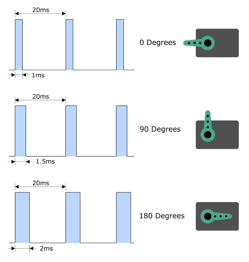
For actuating the barrier gate, we will use a servo. Servo is kind of dc motor with a feedback loop. Depending on the signal provided, the servo rotates to a certain angle. Servos have gearing to provide sufficient torque to hold a certain angular position. The signal provided to the servo is in the form of pulse width modulation (PWM). The PWM signal means there is certain period of pulse with high level and remaining period of low level. Typical frequency of this PWM signal is 50Hz which means signal repeats 50 times every second.
To provide 0⁰ position, a signal is at high for 1ms followed by 19ms of low. Similarly, to provide 180⁰ position, the signal is held high for 2ms followed by 18ms of low. Different periods between 1ms to 2ms of high level provide different angular positions between 0⁰ to 180⁰.
The servo block has 3 terminals as well. Red terminal for 5V power, black terminal for ground and yellow terminal for digital data signal.
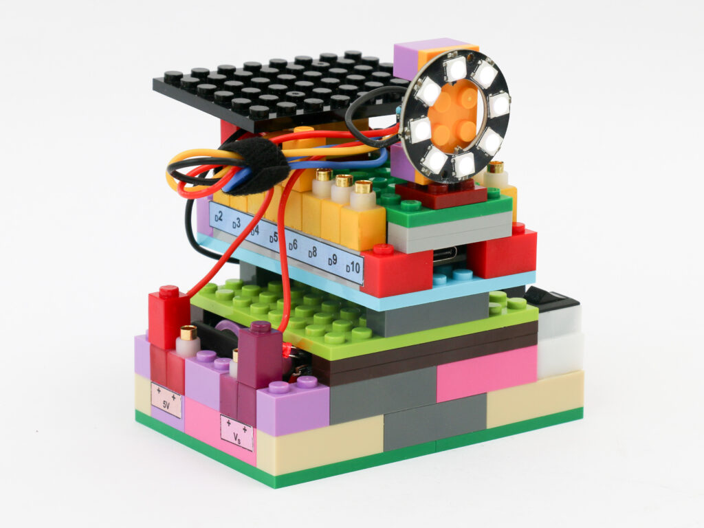
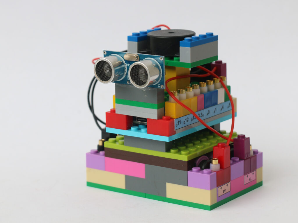
Components
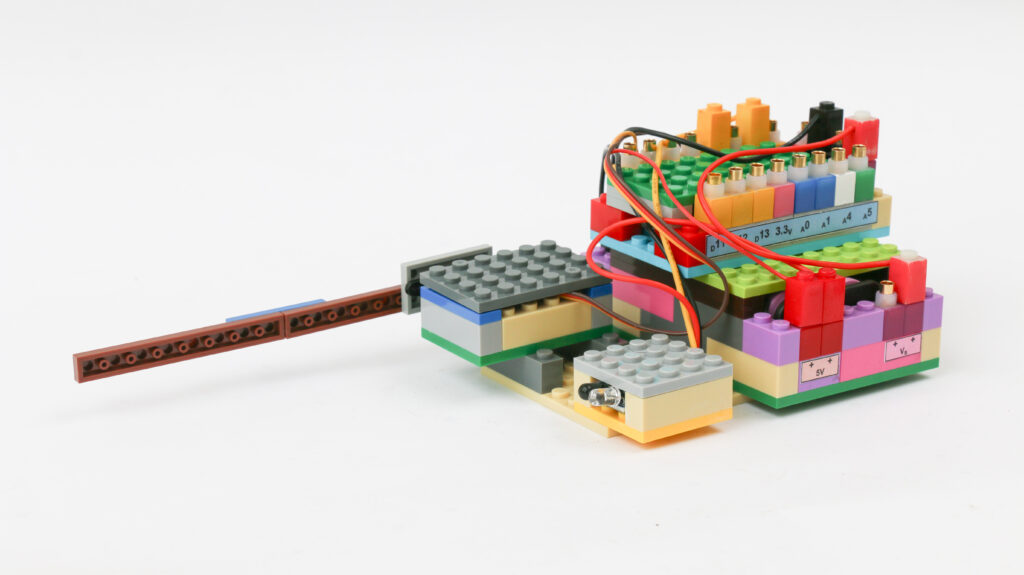
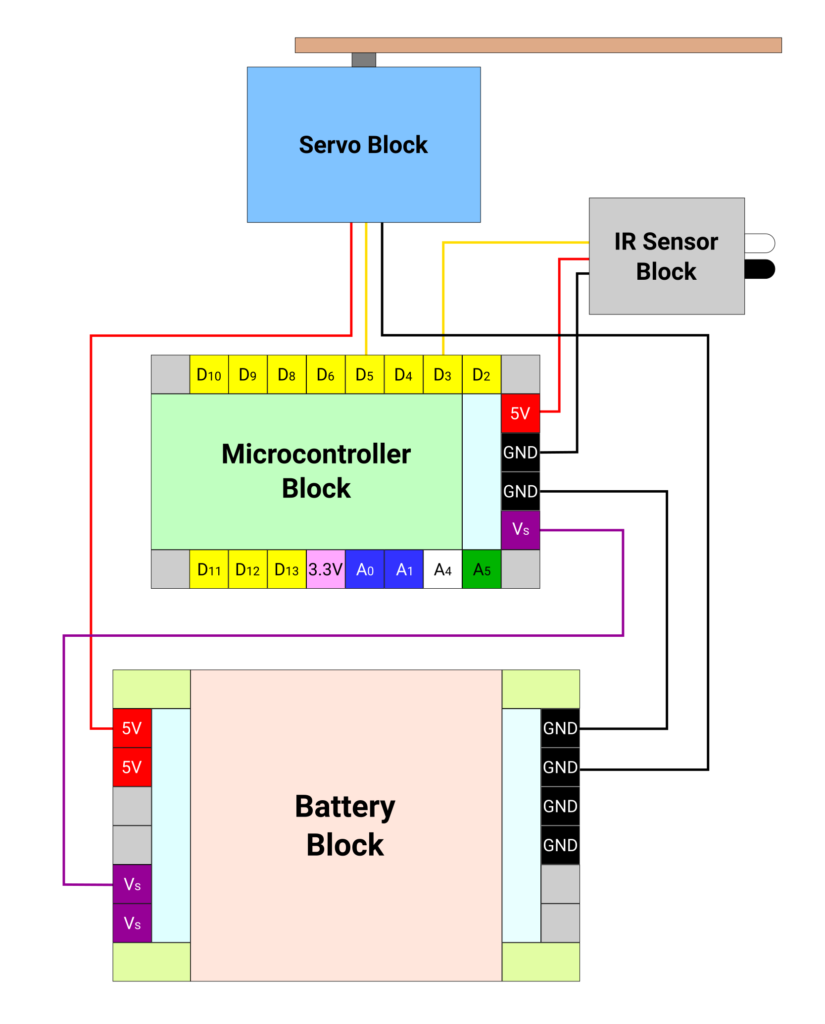
Connections
Connect the Vs pin of microcontroller to Vs pin of battery block. Connect the ground pins of microcontroller block and battery block.
Connect red terminal of IR sensor block to 5V pin on microcontroller block. Connect the black terminal of IR sensor block to – terminal on the microcontroller block. Connect yellow terminal of IR sensor block to pin D3 on microcontroller block.
Connect the red terminal of servo block to 5V pin on the battery block. Connect the black terminal of servo block to – terminal on the battery block. Connect yellow terminal of servo block to pin D5 on microcontroller block.
Coding
We are going to use a library called Servo.h. This library provides simplified way to actuate servo by just providing one argument with an angle to be set on servo instead of providing raw values of PWM signal.
We want to look for the pin value where IR sensor is attached. The pin will continually read 1 or HIGH. When the reading changes to value 0 or LOW, we need to actuate the servo to 90⁰ to open the gate. We need to keep the gate open till the pin reads LOW. Once the pin reads HIGH again, we will provide a delay of 2 seconds to allow the car to pass before closing the gate. After the delay, we want to actuate the servo to be at 0⁰.
/*
   Makernova Robotics 2025
   In this program we use IR sensor to sense obstacle and
   use servo to actuate a gantry gate
*/
#include <Servo.h>  // servo library for ease in servo commands

int IRSensor = 3;  // connect yellow terminal of ir sensor to microcontroller pin D3

Servo myservo;     // create an object called myservo using servo library
int servoPin = 5;  // connect yellow terminal of servo block to microcontroller pin D5

int irstate = 0;      //parameter for current state of IR sensor
int lastirstate = 0;  //parameter for last state of IR sensor
int pos = 180;        // define pos as servo angle

void setup() {
  pinMode(IRSensor, INPUT);  // define IR Sensor pin INPUT
  myservo.attach(servoPin);  // Initiate myservo object
}
void loop() {
  int irstate = digitalRead(IRSensor);  // read the value of IR sensor pin
  if (irstate == 0) {                   // if the IR pin reads low, it means it has detected obstacle
    myservo.write(90);                  //keep the gate open with servo at 90 degrees
    lastirstate = irstate;              // make last state same as current state which is 0
  }

  else if (irstate = 1 && lastirstate == 0) {  // this is when obstacle has passed and IR Pin reads 1
    delay(2000);                               // we add a delay to make sure the car passes before we close the gate
    lastirstate = irstate;                     // we make last ir state same as current ir state which is 1
  } else {                                     // this is default position when ir pin reads high. Keep gate closed
    myservo.write(0);
  }
  delay(50);  // repeat the loop with every 50 ms
}