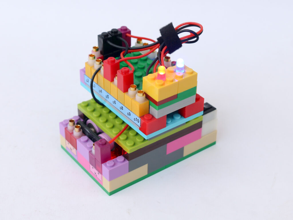
Touchless Fan Speed Control
DC motor can operate at variable speeds depending on the voltage provided to it. DC motor can consume 350mA at no load. At higher loads, say with a fan attached, the current consumption can be even higher. This current level is much higher than the current rating of the microcontroller I/O pins.
In order to control the DC motor via microcontroller, we need to use a transistor. A transistor is a semiconductor component, which acts like an electronic switch. It has 3 terminals; a Base, a Collector & an Emitter. Voltage is applied between collector and emitter. Without any voltage applied at the base, the transistor does not allow any current to pass through between collector & emitter.
When a small voltage applied at the base, the transistor allows current to pass from collector to emitter. Since a small amount of current at base allows much larger current flow through collector to emitter, we can use microcontroller to actuate base pin. The DC motor is connected in series with a transistor and power source.
We can use PWM signal output to base pin which converts to DC motor running under PWM signal. Since the rotating part of motor has inertia, PWM signal causes motor shaft to rotate at different speed, depending on the duty cycle.
For touchless actuation part, we will use the IR proximity sensor with same logic used in the touchless switch project. Every time the proximity sensor detects hand, we will change the motor speed to next level.
Components
- Microcontroller block
- Infrared proximity sensor block
- DC motor block
- Transistor block
- Battery block
- Connectors
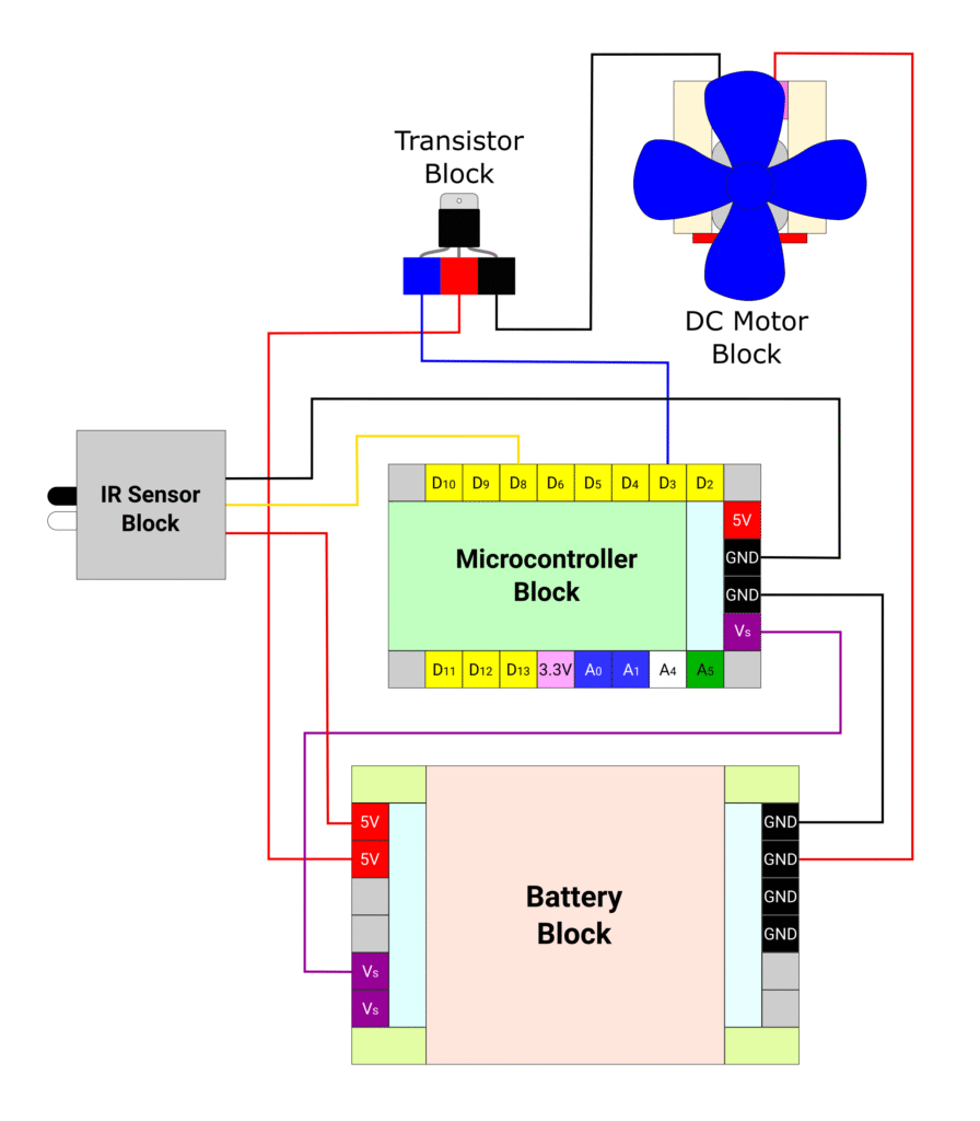
Connections
Connect the battery block Vs pin to the Vs pin of the microcontroller block. Connect any of black (negative) pins on the battery block to one of the negative (black) pin on the microcontroller block.
Connect the base pin (blue) of the transistor block to microcontroller block pin D3. Connect the collector (red) pin of the microcontroller block to battery block 5V pin. Connect emitter (black) pin of the transistor block to the black terminal of DC motor block. Connect the red terminal of DC motor block to battery block ground (black) pin. The DC motor terminals can be reversed to change the rotation direction as needed.
Connect the IR proximity sensor red terminal to battery block 5V pin. Connect the IR proximity sensor black terminal to microcontroller ground (black) pin. Connect the yellow terminal of IR proximity sensor to microcontroller block pin D8.
Code
As mentioned above, we can use similar logic used in touchless switch project to read proximity sensor. Instead of toggling led state, we will use a counter. For each trigger of proximity sensor we increase the counter value. Once the counter value reaches to 3, we will reset the counter value to 0 for next trigger.
We use the counter value to define the PWM value provided to the base pin of the transistor.
/*
 In this project we will use IR proximity sensor as touchless switch
 to toggle through fan speeds using a transistor block to drive it
 Each time the touchless switch is triggered, the fan speed moves in
 sequence Low, Medium, High, off
 Makernova Robotics @2025
*/

const int IRSensor = 8;  // connect ir sensor signal terminal to pin D8
const int fanPin = 3;    // conect the transistor base pin to pin D3
byte state = 1;          // declare variable to read sensor data with starting value HIGH
byte prevstate = 1;      // variable to store previous sensor data with starting value HIGH
byte fanState = 0;       // variable to store LED logic level with starting value LOW

void setup() {
  pinMode(IRSensor, INPUT_PULLUP);  // declare IR Sensor pin as INPUT with internal pull up
  pinMode(fanPin, OUTPUT);          // declare Fan Pin as output
}

void loop() {
  state = digitalRead(IRSensor);  //read the signal from IR sensor

  // when hand is brought near sensor, the sensor sends LOW signal
  // but the previous signal is still HIGH. We use this to trigger change in LED state
  if (state == 0 && prevstate == 1) {
    fanState = fanState + 1;  // increase counter value by 1
    if (fanState > 4) {       // if counter value goes above 3, reset to 0
      fanState = 0;
    }
    prevstate = state;  // make previous & current state same
  }

  // when hand is removed from sensor, the sensor start sending HIGH signal
  // but the previous signal is still LOW.
  if (state == 1 && prevstate == 0) {
    prevstate = state;  // make previous & current state same
  }

  if (fanState == 1) {         // first counter level
    analogWrite(fanPin, 125);  // set speed to 50%
  } else if (fanState == 2) {  // second counter level
    analogWrite(fanPin, 187);  // set speed to 75%
  } else if (fanState == 3) {  // third counter level
    analogWrite(fanPin, 255);  // set speed to 100%
  } else {
    digitalWrite(fanPin, LOW);  // if counter value is 0, switch motor off
  }
  delay(50);  // wait for 50ms before next loop
}